
Page 503 - Battery Reference Book
P. 503
49/4 Methods of charging large nickel-cadmium batteries
49.1 Trickle charge/float charge
To compensate for losses for self-discharge, a trickle
charge current of approx. 50-80mA per lOOA h nom-
inal capacity is essential. Depending on the type of
battery and ambient temperature, the trickle charge
voltage will be 1.35-1.45 Vkell. If charged in paral-
lel using a constant potential of 1.40 Vkell, the trickle
charge current, depending on the ambient temperature, El
will be 50-1OOmA per lOOAh nominal capacity. If,
in addition to the self-discharge, there is a low or tem- Battery
porary load connected to the battery, a float charge
is essential. The float charge current should be from Figure 49.4 Switch-tripping operation of a large vented
120 to 150mA per lOOAh nominal capacity. The cell nickel-cadmium battery (Courtesy of Chloride Batteries)
voltage will be 1.4-1.45 V. The best float charge volt-
age should be found by experiment, the criterion being
the loss of electrolyte consistent with having a fully
charged battery. If there is a continuous trickle or float
charge, it is essential to make an equalization charge Load
with a charging current of 15 every 3-6 months for
15 h or a boost charge depending on the characteristic
of the charger to ensure full nominal capacity.
49.2 Charge/discharge operations on
large vented nickel-cadmium
batteries
1. Churge/dischurge operution The charge and dis- Battery
charge of the battery is arranged separately by con- Figure 49.5 Automatic recharging of a large vented nickel-
necting the battery to the charger or by connecting cadmium battery (Courtesy of Chloride Batteries)
the battery to the load (Figure 49.3).
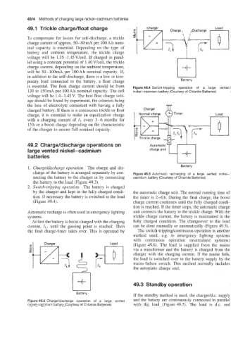
2. Switch-tripping operation The battery is charged
by the charger and kept in the fully charged condi- the automatic charge unit. The normal running time of
tion. If necessary the battery is switched to the load the timer is 2-6 h. During the final charge, the boost
(Figure 49.4). charge current continues until the fully charged condi-
tion is reached. If the timer stops, the automatic charge
Automatic recharge is often used in emergency lighting unit connects the battery to the trickle charge. With the
systems. trickle charge current, the battery is maintained in the
At first the battery is boost charged with the charging fully charged condition. The changeover to the load
current, ZL. until the gassing point is reached. Then can be done manually or automatically (Figure 49.5).
the final charge-timer takes over. This is operated by The switch-trippinglcontinuous operation is another
method used, e.g. in emergency lighting systems
with continuous operation (maintained systems)
(Figure 49.6). The load is supplied from the mains
via a transformer and the battery is charged from the
charger with the charging current. If the mains fails,
the load is switched over to the battery supply by the
mains-failure switch. This method normally includes
the automatic charge unit.
49.3 Standby operation
If the standby method is used, the charger1d.c. supply
Figure 49.3 Chargddischarge operation of a large vented and the battery are continuously connected in parallel
nickel-cadmium battery (Courtesy of Chloride Batteries) with the load (Figure 49.7). The load is d.c. and