
Page 63 - 02. Subyek Computer Aided Design - Beginner’s Guide to SOLIDWORKS 2019- Level 1 by Alejandro Reyes
P. 63
Part Modeling
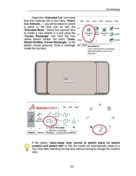
Select the "Extruded Cut" command
from the Features tab or the menu "Insert, ~ Edit View Insert Tools Window Help
Cut, Extrude ... "; you will be asked to select
a plane or flat face just as with the ~ Swept
I Se
"Extruded Boss." Select the topmost face
to create a new Sketch in it and using the ~se Extruded Revolved ~ Lofted
Cut Cut
"Corner Rectangle" tool from the now
visible Sketch toolbar, the menu "Tools, s/Base ~ Bound
Sketch Entities, Corner Rectangle," or the
ate
sketch mouse gestures. Draw a rectangle .___ _ Dim
___, Extruded ,Cut
inside the top face. Cuts a solid model by extruding a
sketched profile in one or two
directions.
. ~ ...
, ..
•
I
i
•
I
i
•
I
i
•
I
•
I
•
I
•
I
•
I
•
I
•
I
•
I
•
.
I .
~
;jS SOLIDWORKS File Edit View
/
Comer Rectartgle
Sketches a recta n g I e.
l Features I Sketch I EV d iUd l t= .luuuvv ur..l\..l J-\ud-lns
• I
If the option "Auto-rotate view normal to sketch plane on sketch
creation and sketch edit" is ON, the model will automatically rotate to a
Top View after selecting the top face without having to change the model's
•
VIeW.
53