
Page 101 - Biaxial Multiaxial Fatigue and Fracture
P. 101
86 L. SUSMEL AND N. PETRONE
an extension of the Mandell semi-log linear equation and, finally, the criterion due to Smith &
Pascoe is capable of modelling three different fatigue damage mechanisms: the rectilinear
cracking, the shear deformation along the fibre plane and the combined rectilinear cracking and
matrix shear deformation.
These approaches are clearly developed for composites, but when the degree of anisotropy is
not so high, different methods are again suggested. The criterion proposed by Lin et al. [28, 291
can be mentioned as a valid criterion to apply in this kind of situations. This method is based on an
original employment of the strain vector.
Aim of the present paper is the validation of the Susmel and Lazzarin's criterion on a widely
used industrial aluminium alloy showing a slight degree of anisotropy to confirm if the
employment of specific models for anisotropic materials can be avoided when subjected to in-
phase and out-of-phase multiaxial loadings.
FUNDAMENTALS OF THE MODIFIED WOHLER CURVES METHOD
The theoretical frame of the Susmel and Lazzarin's criterion is based on a combined use of a
modified Wohler diagram and the initiation plane concept [21].
The theory of deformation in single crystal has been employed to give a physical interpretation
of the fatigue damage: in a polycrystal this depends on the maximum shear stress amplitude, tar
(determined by the minimum circumscribed circle concept [30]) and on the maximum stress u",,,,~~
normal to the plane of maximum shear stress amplitude (initiation plane) [21].
A
ZA,Ref(P1)
' ZA,Ref (pi)
J
increasing p 1
!
I
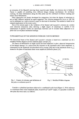
Fig. 1. Frames of reference and definition of Fig. 2. Modified Wohler diagram.
the polar co-ordinates I# and 9.
Consider a cylindrical specimen subjected to a multiaxial cyclic load (Figure 1). With reference
to a maximum shear stress amplitude plane, located by $* and 8* angles, it is possible to define for
this plane the stress ratio p as follows: