
Page 142 - Biaxial Multiaxial Fatigue and Fracture
P. 142
The InJuence of Static Mean Stresses Applied Normal to the Maximum Shear Planes in ._. 127
‘Amplitude
‘Amplitude R, =-1
R =-I
1 t!
.*, +
int * Mean
4 I
int cr Mean
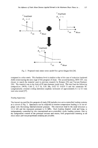
Fig. 2. Proposed static mean stress model for a given fatigue life [26].
compared to softer steels. This hardness level is similar to that of the case of induction hardened
shafts tested during the next stage of this program of study. The second hardness, BHN 203, was
chosen to match the material used in previous research by Bonnen [25] and Varvani-Farahani
[26]. The material was in the form of 65 rnm diameter round stock. The steel had the following
composition (Wt%): 0.46 C, 0.17 Si, 0.81 Mn, 0.027 P, 0.0235 S and the remainder Fe.
Longitudinally oriented (rolling direction) sulphide inclusions of approximately 0.1 to 0.3 mm
were also noted [27].
Testing Apparatus
The biaxial rig used for this program of study [28] includes two servo-controlled loading systems
as is shown in Fig. 3. Specimens can be subjected to tension-compression loading in or out-of-
phase with fluctuating internal-external pressure. The maximum load in the axial direction is
11 1.2 kN and the maximum pressure is 21 MPa. Each loading channel, axial and hoop, is
independently controlled by two conventional servo-controlled, cyclic loading systems. Due to
the independent control of the principal stresses and strains, both proportional straining at all
stress ratios and non-proportional straining are possible.