
Page 293 - Biaxial Multiaxial Fatigue and Fracture
P. 293
An Analysis of Elasto-Plastic Strains and Strases in Notched Bodies Subjected to Cyclic _.. 211
The nominal stresses in the net cross section were determined as:
F 2T
g,, =- and r,, = ___
E(R - t)” z(R - t)’
The elastic-plastic finite element stress and strain stress results were obtained using the
ABAQUS finite element package with built-in plasticity model.
at
The torque T induced the ‘linear elastic’ shear stress ~ 2 3 ~the notch tip and the axial load F
induced the normal axial stress component 02; and the normal hoop stress ~33~. The fictitious
elastic normal stress components maintained constant ratio throughout the entire loading history,
The
i.e. CS~</O~~=CO~S~. increments of the hypothetical “elastic” stress components AcJ~~~, Ac2;
and 803; and associated strains were used as the input into the equation set (12). Two linear
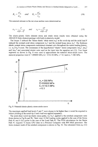
segments as shown in Fig. 8 were used to approximate the material stress-strain curve. The
material properties were E = 200000 MPa, El= 4142.50 MPa, v = 0.3 and cy = 200 MPa.
oY = 200 MPa
E=200000 MPa
E,=4142.5 MPa
~0.3
I
b
E
Fig. 8. Material elastic-plastic stress-strain curve
The maximum applied load levels F and T were chosen to be higher than it would be required to
induce yielding at the notch tip if each load was applied separately.
The axial-shear notch tip elastic stress paths, ~~:-0~3e, applied to the notched component were
those shown in Fig.9a and 9b. There were 10 111 Ioading cycles applied in the case of the Stress
Path #1 and 6 full cycles in the case of the Load Path #2. The FEM calculations for the Stress
Path #1 required 72 hours CPU time on a Personal Computer with 800 MHZ processor. The
finite element mesh of the notched component is shown in Fig. 10. The calculated from eq. (12)