
Page 274 - Biofuels Refining and Performance
P. 274
Fuel Cells 253
Electric current
e − e −
Depleted − Water
fuel e e −
+
H
Η Ο
2
H 2
O 2
+
H
Fuel Air in Hydrogen molecule
Anode Cathode Oxygen molecule
Electrolyte Gas diffusion layer Water
Gas diffusion layer
+
Cathode catalyst Hydrogen ion (H )
Anode catalyst layer
layer
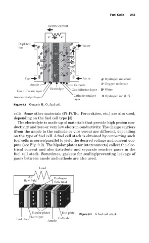
Figure 9.1 Generic H 2 -O 2 fuel cell.
cells. Some other materials (Pt-Pt/Ru, Perovskites, etc.) are also used,
depending on the fuel cell type [3].
The electrolyte is made up of materials that provide high proton con-
ductivity and zero or very low electron conductivity. The charge carriers
(from the anode to the cathode or vice versa) are different, depending
on the type of fuel cell. A fuel cell stack is obtained by connecting such
fuel cells in series/parallel to yield the desired voltage and current out-
puts (see Fig. 9.2). The bipolar plates (or interconnects) collect the elec-
trical current and also distribute and separate reactive gases in the
fuel cell stack. Sometimes, gaskets for sealing/preventing leakage of
gases between anode and cathode are also used.
Load
Air
Hydrogen
flow field flow field
Bipolar plates End plate
Figure 9.2 A fuel cell stack.
Electrolyte
End plate Cathode
Anode