
Page 167 - Biomass Gasification, Pyrolysis And Torrefaction Practical Design and Theory
P. 167
144 Biomass Gasification, Pyrolysis and Torrefaction
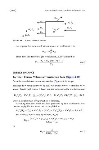
Q loss
W g
W g ,T gi
W v W f ,T 0
Q gen
W’ g ,T go
W vl
W t ,T o
FIGURE 4A.1 Control volume of torrefier.
Air required for burning oil with an excess air coefficient, α is
A
W air 5 α W oil
F
From here, the fraction of gas recirculation, X, is calculated as:
½W g 2 W oil :ðαðA=FÞ 1 1Þ
X 5 (A.4)
W 0 g
ENERGY BALANCE
Torrefier: Control Volume of Torrefaction Zone (Figure 4.11)
From the mass balance around the torrefier (Figure 4A.1), we get:
Enthalpy in 1 energy generated by mild exothermic process 5 enthalpy out 1
energy loss through reactor 1 latent heat carried away by the moisture content
W g C g T gi 1W f C b T o 1Q gen 5ðW g C g 1W v C v 1W vl C g ÞT g0 1W t C d T t 1Q loss 1W v L
where L is latent heat of vaporization of moisture.
Assuming that heat losses and heat generated by mild exothermic reac-
tion are negligible, the above can be simplified as:
W g C g ðT gi T g0 Þ 1 W f C b T 0 ðW v C v 1 W vl C g ÞT g0 W t C d T t W v L 5 0
So, the mass flow of heating medium, W g ,is
ðW v C v 1 W vl C g ÞT g0 1 W t C d T t 2 W f C b T 0 1 W v L
W g 5
C g ðT gi 2 T g0 Þ
or
A
W g 5 (A.5)
C g ðT gi 2 T g0 Þ