Page 168 - Biomass Gasification, Pyrolysis And Torrefaction Practical Design and Theory
P. 168

Chapter | 4  Torrefaction                                    145


                                  Recycled
                                  flue gas  X.W’ ,T go
                                              g
                                                     W ,T’’ o
                                                      oil
                                         Burner
                              W ,T gi
                                g
                                          with
                                        dilution
                                                    W ,T’ o air
                                                      air
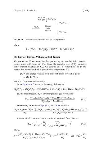
             FIGURE 4A.2 Control volume of burner with gas mixing chamber.

             where,
                       A 5 ðW v C v 1 W vl C g ÞT g0 1 W t C d T t 2 W f C b T 0 1 W v L


             Oil Burner: Control Volume of Oil Burner

             We assume that X fraction of the flue gas leaving the torrefier is fed into the
             burner along with fresh air W air . Since the recycled gas (XW ) contains
                                                                   0
                                                                   g
             some unburnt volatiles (XW vl ), we assume this to supplement oil in the
             burner. We assume fuel oil is preheated to temperature Tv 0 .
                  Q vl 5 heat energy released from the combustion of volatile gases
                     5 XW vl LHV vl η

             where η is combustion efficiency.
                From Figure 4A.2, we write the energy balance as:

                          0                          0
             W g C g T gi 5 XW C g T g0 1 XW vl LHV vl η 1 W air C a T 1 W oil LHVη 1 W oil C oil Tv 0
                          g                          0
                So, the mass fraction, X, of torrefier product gas recycled is
                                           0
                           W g C g T gi αðA=FÞC a T 2 W oil LHVη 2 W oil C oil Tv 0
                                           0
                       X 5                                              (A.6)
                                     W C g T g0 1 W vl LHV vl η
                                       0
                                       g
                Substituting values from Eqs. (A.4) and (A.6), we have
                                                        0
             ½W g 2W oil ðαðA=FÞ11ފ  W g C g T gi 2W oil αðA=FÞC a :T 2W oil LHVη2 Woil C oil Tv 0
                                                        0
                                5
                     W  0                      W C g T g0 1W vl LHV vl η
                                                0
                       g                        g
                Amount of oil consumed in the burner is calculated from here as:
                                 1     W g       C g T gi
                         W oil 5    3               0       2 1         (A.7)
                               K 2 P   W g 0  C g T g0 1 VL LHV vl η
                                                    fr
             where,

                           0
                 αðA=FÞC a :T 1 LHVη 1 C oil Tv 0  ðαA=F 1 1Þ         0  W vl
                           0
             K5                              ;  P5             and VL 5
                     W C g T g0 1 W vl LHV vl η       W  0 g          fr  W  0 g
                       0
                       g
   163   164   165   166   167   168   169   170   171   172   173