
Page 102 - Biomimetics : Biologically Inspired Technologies
P. 102
Bar-Cohen : Biomimetics: Biologically Inspired Technologies DK3163_c003 Final Proof page 88 21.9.2005 11:40pm
88 Biomimetics: Biologically Inspired Technologies
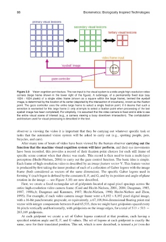
Figure 3.9 Vision cognition architecture. The raw input to the visual system is a wide-angle high-resolution video
camera (large frame shown in the lower right of the figure). A subimage, of a permanently fixed size (say
1024 1024 pixels) of a single video frame (shown as a square within the large frame), termed the eyeball
image, is determined by the location of its center (depicted by the intersection of crosshairs), known as the fixation
point. The gaze controller uses the entire large frame to select a single fixation point, if it deems that such a
selection is warranted for this large frame (it only attempts to select a fixation point when processing of the last
eyeball image has been completed). For simplicity, it is assumed that the video camera is fixed and is able to see
the entire visual scene of interest (e.g., a camera viewing a busy downtown intersection). The confabulation
architecture used for visual processing is described in the text.
observer is viewing the video it is important that they be carrying out whatever specific task or
tasks that the automated vision system will be asked to carry out (e.g., spotting people, pets,
bicycles, and cars).
After many tens of hours of video have been viewed by the human observer carrying out the
function that the machine visual cognition system will later perform, and their eye movements
have been recorded, this provides a record of their fixation point choices for each still frame of
specific scene content when that choice was made. This record is then used to train a multi-layer
perceptron (Hecht-Nielsen, 2004) to carry out the gaze control function. The basic idea is simple.
Each frame of high-resolution video is described by an image feature vector V. This feature vector
is produced by first taking the inner product of each of a collection of Gabor logons with the image
frame (both considered as vectors of the same dimension). The specific Gabor logons used in
forming V (each logon is defined by the constants E, F, and G, and by its position and angle of plane
rotation in the image — see Figure 3.10) are now described.
First, we create a fixed rectangular set of gridpoints located at equal pixel spacings across the
entire high-resolution video camera frame (Caid and Hecht-Nielsen, 2001, 2004; Daugman, 1985,
1987, 1988a,b; Daugman and Kammen, 1987; Hecht-Nielsen, 1990; Hecht-Nielsen and Zhou,
1995). For example, if each video camera image frame were a 8,192 8,192 pixel digital image,
with a 16-bit panchromatic grayscale, or equivalently, a 67,108,864-dimensional floating point real
vector with integer components between 0 and 65,535, then we might have gridpoints spaced every
16 pixels vertically and horizontally, with gridpoints on the image edges, for a total of 513 513 ¼
263,169 gridpoints.
At each gridpoint we create a set of Gabor logons centered at that position, each having a
specified rotation angle and E, F, and G values. The set of logons at each gridpoint is exactly the
same, save for their translated position. This set, which is now described, is termed a jet (von der