
Page 164 - Boiler_Operators_Handbook,_Second_Edition
P. 164
Refrigeration & AC 149
of the evaporator to help cool the liquid refrigerant. cooler to overcome that differential. If the pressure
The cool gas is simply superheated a little more as it drop in the liquid refrigerant tubing introduced an-
absorbs the heat from the liquid. It’s also possible to other 15 psi the combination would approach the nor-
have an independent subcooler to cool the liquid re- mal design of 10° subcooling. Then I would remember
frigerant. that since the liquid line ran up the building on the
Subcooling is necessary to ensure the liquid re- inside it would be cooled by the conditioned room
mains a liquid until it has exited the throttling device. temperature. That might not help in a taller building.
If the liquid is not subcooled sufficiently it can breach
saturation conditions as the pressure in the liquid Measuring superheat and subcooling
tubing drops due to friction or changes in elevation. Unlike our boiler plants refrigeration systems do
When that happens small bubbles of refrigerant vapor not always have pressure gauges and thermometers
form in the liquid line and, because the vapor uses up mounted in the piping. When there are gauges or ther-
more space than liquid, result in increased velocity in mometers it’s an indication that the reading should be
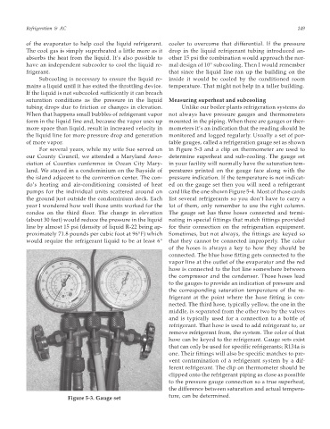
the liquid line for more pressure drop and generation monitored and logged regularly. Usually a set of por-
of more vapor. table gauges, called a refrigeration gauge set as shown
For several years, while my wife Sue served on in Figure 5-3 and a clip on thermometer are used to
our County Council, we attended a Maryland Asso- determine superheat and sub-cooling. The gauge set
ciation of Counties conference in Ocean City Mary- in your facility will normally have the saturation tem-
land. We stayed in a condominium on the Bayside of peratures printed on the gauge face along with the
the island adjacent to the convention center. The con- pressure indication. If the temperature is not indicat-
do’s heating and air-conditioning consisted of heat ed on the gauge set then you will need a refrigerant
pumps for the individual units scattered around on card like the one shown Figure 5-4. Most of those cards
the ground just outside the condominium deck. Each list several refrigerants so you don’t have to carry a
year I wondered how well those units worked for the lot of them, only remember to use the right column.
condos on the third floor. The change in elevation The gauge set has three hoses connected and termi-
(about 30 feet) would reduce the pressure in the liquid nating in special fittings that match fittings provided
line by almost 15 psi (density of liquid R-22 being ap- for their connection on the refrigeration equipment.
proximately 71.8 pounds per cubic foot at 96°F) which Sometimes, but not always, the fittings are keyed so
would require the refrigerant liquid to be at least 6° that they cannot be connected improperly. The color
of the hoses is always a key to how they should be
connected. The blue hose fitting gets connected to the
vapor line at the outlet of the evaporator and the red
hose is connected to the hot line somewhere between
the compressor and the condenser. Those hoses lead
to the gauges to provide an indication of pressure and
the corresponding saturation temperature of the re-
frigerant at the point where the hose fitting is con-
nected. The third hose, typically yellow, the one in the
middle, is separated from the other two by the valves
and is typically used for a connection to a bottle of
refrigerant. That hose is used to add refrigerant to, or
remove refrigerant from, the system. The color of that
hose can be keyed to the refrigerant. Gauge sets exist
that can only be used for specific refrigerants; R134a is
one. Their fittings will also be specific matches to pre-
vent contamination of a refrigerant system by a dif-
ferent refrigerant. The clip on thermometer should be
clipped onto the refrigerant piping as close as possible
to the pressure gauge connection so a true superheat,
the difference between saturation and actual tempera-
ture, can be determined.
Figure 5-3. Gauge set