
Page 290 - Boiler plant and distribution system optimization manual
P. 290
Steam Traps 275
There is a wide range of temperature mea- Table 14.12 is a steam trap inspection check-
surement equipment. It ranges from infrared de- list to aid personnel in their trap checking rou-
vices, which are handy for reading temperatures tines. They should also investigate the possibility
from a distance and at inaccessible locations. of trap misapplication. Table 14.13 will be helpful
Standard pyrometers and surface thermocouples for this purpose.
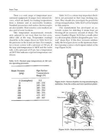
are also suitable. Heat sensitive color markers are One manufacturer has developed an au-
also used at some locations. tomatic system for detecting if steam traps are
Take temperature measurements immedi- blowing-off an excessive amount of steam. The
ately adjacent to, not more than two feet away, sensor chamber (Figure 14.23) has a small orifice
either side of the trap. Temperature readings in a division plate which is designed to pass “nor-
should be in the ranges shown in Table 14.11 for mal” steam flow. If this flow increases substan-
the pressures in the in and out lines. For example, tially, the level goes down on the upstream cham-
for a steam system with a pressure of 150 psi, if ber exposing a sensor which signals failure of the
the trap inlet temperature is 340°F and the outlet trap (Figure 14.24).
side, with a pressure of 15 psi, has a temperature
of 230°F this indicates expected temperature con-
ditions.
Table 14.11—Normal pipe temperatures at 348 vari-
ous operating pressures.
Figure 14.23—Sensor chamber for trap monitoring in-
stallation. Note the orifice and weir (partition plate).
Figure 14.24—Trap monitoring installation.