Page 81 - Boiler plant and distribution system optimization manual
P. 81

66                                                  Boiler Plant and Distribution System Optimization Manual


                                                                    on which is in use. The volume change, percent
                                                                    CO  or O , can be read in percent on a convenient
                                                                             2
                                                                       2
                                                                    scale.


                                                                    FINDING STACK LOSSES

                                                                         By measuring the net stack temperature
                                                                    (Stack temperature—combustion air tempera-
                                                                    ture), combustion tables or slide rule (Figure 7.9)
                                                                    can be used to determine flue gas losses.


                                                                    Measuring Flue gas Oxygen on a
                                                                    Continuous Basis
                                                                         There are three common methods of measur-
                                                                    ing oxygen in flue gas on a continuous basis. The
                                                                    paramagnetic sensor, the wet electrochemical cell
                       Figure 7.7—Fyrite CO  or O  indicator        and the zirconium oxide ceramic cell.
                                           2
                                                2
                these gases. They are a very practical, simple,
                rugged and economical approach to combus-
                tion testing. Also, they are very
                useful for backing-up the more
                complex  instruments  which
                may develop errors and faults
                from time to time.
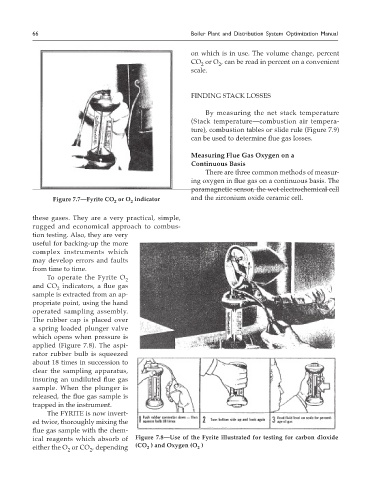
                     To  operate  the  Fyrite  O
                                               2
                and CO  indicators, a flue gas
                        2
                sample is extracted from an ap-
                propriate point, using the hand
                operated sampling assembly.
                The rubber cap is placed over
                a spring loaded plunger valve
                which opens when pressure is
                applied (Figure 7.8). The aspi-
                rator rubber bulb is squeezed
                about 18 times in succession to
                clear the sampling apparatus,
                insuring an undiluted flue gas
                sample.  When  the  plunger  is
                released, the flue gas sample is
                trapped in the instrument.
                     The FYRITE is now invert-
                ed twice, thoroughly mixing the
                flue gas sample with the chem-
                ical  reagents  which  absorb  of   Figure 7.8—Use of the Fyrite illustrated for testing for carbon dioxide
                either the O  or CO , depending   (CO  ) and Oxygen (O  )
                                                      2
                                                                      2
                           2
                                   2
   76   77   78   79   80   81   82   83   84   85   86