
Page 80 - Boiler plant and distribution system optimization manual
P. 80
Combustion Analysis 65
FLUE GAS HEAT LOSS FLUE GAS MEASUREMENT
ORSAT TESTING
Flue gas heat loss is the largest single energy
loss in every combustion process. It is generally One of the earliest methods of measurement
impossible to eliminate flue gas heat losses be- is still in use today. The Orsat test is a manual-
cause the individual constituents of flue gas all ly-performed test in which a flue gas sample is
enter the system cold and leave at elevated tem- passed successively through a series of chemical
peratures. Flue gas heat loss can be minimized by reagents. The chemicals each absorb a single
reducing the amount of excess air supplied to the gas constituent, usually carbon dioxide, oxygen,
burner. and carbon monoxide. After the sample passes
Flue gas heat loss increases with both in- through each reagent, its volume is accurately
creasing excess air and temperatures. As both the measured. The reduction in volume indicates the
carbon dioxide and oxygen level in flue gases are amount of gas that was originally in the sample.
directly related to the amount of excess air sup- There are several disadvantages to using the
plied, either a CO or an O flue gas analyzer can Orsat flue gas testing apparatus:
2
2
be used to measure this loss. However, in recent
a. It is slow, tedious work
years, CO analysis has fallen out of favor.
2
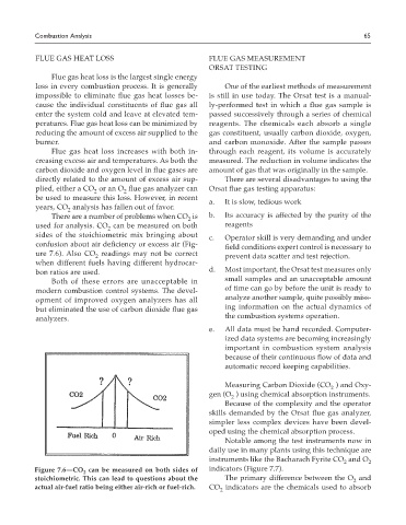
There are a number of problems when CO is b. Its accuracy is affected by the purity of the
2
used for analysis. CO can be measured on both reagents
2
sides of the stoichiometric mix bringing about c. Operator skill is very demanding and under
confusion about air deficiency or excess air (Fig- field conditions expert control is necessary to
ure 7.6). Also CO readings may not be correct prevent data scatter and test rejection.
2
when different fuels having different hydrocar-
bon ratios are used. d. Most important, the Orsat test measures only
Both of these errors are unacceptable in small samples and an unacceptable amount
modern combustion control systems. The devel- of time can go by before the unit is ready to
opment of improved oxygen analyzers has all analyze another sample, quite possibly miss-
but eliminated the use of carbon dioxide flue gas ing information on the actual dynamics of
analyzers. the combustion systems operation.
e. All data must be hand recorded. Computer-
ized data systems are becoming increasingly
important in combustion system analysis
because of their continuous flow of data and
automatic record keeping capabilities.
Measuring Carbon Dioxide (CO ) and Oxy-
2
gen (O ) using chemical absorption instruments.
2
Because of the complexity and the operator
skills demanded by the Orsat flue gas analyzer,
simpler less complex devices have been devel-
oped using the chemical absorption process.
Notable among the test instruments now in
daily use in many plants using this technique are
instruments like the Bacharach Fyrite CO and O
2
2
Figure 7.6—CO can be measured on both sides of indicators (Figure 7.7).
2
stoichiometric. This can lead to questions about the The primary difference between the O and
2
actual air-fuel ratio being either air-rich or fuel-rich. CO indicators are the chemicals used to absorb
2