
Page 215 - Bridge and Highway Structure Rehabilitation and Repair
P. 215
190 SECTION 2 STRENGTHENING AND REPAIR WORK
Resultant Load
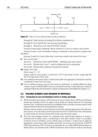
Figure 5.1 Position of 3-axle defl ection truck for maximum defl ection.
Strength III: Wind velocity exceeding 90 KM/h (no signifi cant LL)
Strength IV: Very high DL/LL ratio for large span bridges
Strength V: Normal use with wind of 90 KM/h velocity
Extreme Events (major earthquake, flood, collision of a vessel or vehicle, and ice fl ow)
Extreme Event I: Load combination relating to earthquake is determined on a project-spe-
cifi c basis.
Extreme Event II: Ice load, collision by vessels and vehicles with reduced live load.
9. Service limit state:
Service I: Normal use with wind 90 KM/h 6 deflection and crack control
Service II: Related only to steel - control yielding and slip in connections
Service III: Related only to tension in prestressed concrete.
10. Fatigue limit state:
Stress range, f 3 1.0
Fatigue loads for steel girders: A load factor of 0.75 and trucks at lower weight than the
HL-93 design truck will be used.
11. User defined construction loads: Construction loads with appropriate load factors shall be
considered for short-term live loads.
12. Use of a deflection design truck to limit maximum deflections: A standard defl ection rating
vehicle is used. AASHTO LRFD code has prescribed a moving 72 kips deflection vehicle (a
variation of the basic HS-20 truck) to compute maximum live load deflection (Figure 5.1).
5.2 UTILIZING ULTIMATE LOAD BEHAVIOR OF MATERIALS
5.2.1 Introduction to Load and Resistance Factors in Rating and Design
1. While allowable stress design (ASD) is based on use of a safety factor, LRFD uses both load
factors and resistance factors. It captures much of the post elastic behavior for computing
member sizes. Load factors are based on probability theory and also resistance factors from
material behavior observed during laboratory testing.
Primary analysis remains unfactored and is modified by applying appropriate load and resis-
tance factors. Also, the history of stress development from no load to full load is maintained,
as small strains are assumed during both elastic and post-elastic ranges.
2. The load and resistance factors are calibrated from actual bridge statistics to ensure a
uniform level of safety. Hence, transitioning to load and resistance factor is to produce
consistent levels of reliability across a broad range of designs. It ensures that by applying
appropriate conservatism where needed, significant cost savings can be realized. AASHTO
LRFD Specifications 2007, Section 4 recommends the use of the LRFD method based on
plastic theory and ultimate loads. LRFD incorporates state-of-the-art analysis and design