
Page 220 - Bridge and Highway Structure Rehabilitation and Repair
P. 220
CHAPTER 5 LOAD AND RESISTANCE FACTOR RATING AND REDESIGN 195
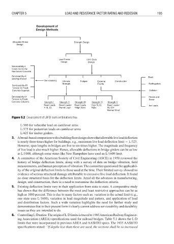
Development of
Design Methods
Figure 5.2 Development of LRFD load combinations tree.
L/300 for vehicular load on cantilever arms
L/375 for pedestrian loads on cantilever arms
L/425 for timber girders.
3. A broad-based comparison with a building floor design shows that allowable live load defl ection
is nearly three times higher for buildings, e.g., maximum live load defl ection limit 3 L/325.
However, span lengths in bridges are five to ten times higher. The magnitude and frequency
of live load is also much higher. Hence, allowable deflections in bridge girders can be as low
as L/1000, although some states like New Hampshire have used an L/1600 limit.
4. A committee of the American Society of Civil Engineering (ASCE) in 1958 reviewed the
history of bridge deflection limits, along with a survey of data on bridge vibration, fi eld
measurements, and human perception of vibration. The committee questioned the applicabil-
ity of the original deflection limits to those used at the time. Their limited survey showed no
evidence of serious structural damage attributable to excessive live load deflection. It found
no clear structural basis for the deflection limits. Amid all the advances in manufacturing,
design, and construction, there is a need to reexamine the defl ection criteria.
5. Existing deflection limits vary in their application from state to state. A comparative study
has shown that the difference between the most and least restrictive approaches can be as
high as 1000 percent. This is due to many factors such as: variation in the actual limit (e.g.,
one state uses L/1600), variation in load magnitude and pattern, and application of load
and distribution factors. Such a wide variation highlights the need for further study and
demonstrates that in their present form it clearly cannot address serviceability and durability
issues as they are intended to do.
6. Controlling L/D ratios: The origin of L/D limits is traced to 1905 American Railway Engineer-
ing Association (AREA) specifications used for railroad bridges. Table 5.1 shows the L/D
limits that were incorporated in previous AREA and AASHTO specs. The 1935 AASHTO
specifi cations stated: “If depths less than these are used, the sections shall be so increased