
Page 224 - Bridge and Highway Structure Rehabilitation and Repair
P. 224
CHAPTER 5 LOAD AND RESISTANCE FACTOR RATING AND REDESIGN 199
6. Method of computing defl ections: Deflections affect bending moment and shear force dis-
tribution. Live load deflections are usually computed by one of the following methods:
• Stiffness matrices.
• Strain energy.
• Double integration method.
• Harmonic analysis.
• Finite difference method.
• Finite element method.
The current method prescribed by AASHTO is using a line girder and applying multiple
lane reductions. There are approximations in the method of applying live load distribution
from each lane for load sharing on the single girder under consideration. Code defl ection
calculations are based on the use of distribution coefficients (DF), which may not give a true
deflection value in all cases due to the complexity of bridge geometry. It may be desirable to
calibrate the line girder code method against a three-dimensional model using the stiffness
method. Software such as SAP2000 or ADINA may be used.
5.3.5 Large Deflections in Single Spans
Large deflections in a single span truss (Figure 5.5) require nonlinear analysis since the load
deflection curve becomes nonlinear when compared to continuous span defl ections.
1. Large deflection causes fracture and debonding of the wearing surface due to excessive work
done. In timber construction, fasteners loosen.
2. Stiffness of entire deck width considered:
Defl ection DF 3 Number of lanes/number of lanes
3. Additional shear deflection occurs under heavy truck load, especially for cantilever over-
hangs.
4. Arching action at the supports in composite deck slabs may reduce defl ection.
5.3.6 Primary Effects of Defl ections
1. The two design criteria for strength and deflection are linked together. When there is no
deflection, there is no stress. The higher the deflection, the higher the slope and resulting
curvature (Figure 5.5). An increase in curvature gives rise to an increase in bending moment
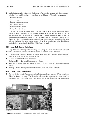
Figure 5.4 Use of three column hammerhead piers in place of wall piers.