
Page 225 - Bridge and Highway Structure Rehabilitation and Repair
P. 225
200 SECTION 2 STRENGTHENING AND REPAIR WORK
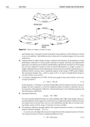
Figure 5.5 Positive and negative curvature in trusses.
and bending stress. Strength is based on ultimate load conditions, while deflection is based
on service conditions. Total deflection due to dead and live load plus impact will not exceed
yield stress.
2. Sophistications in today’s bridge designs combined with advances in development of high
performance materials of various grades demands an equally advanced and sophisticated
approach to considering serviceability and durability requirements such that it will not negate
the economic benefits of advances made in material development. A simple example of a
simply supported beam is used to demonstrate why present serviceability requirements (e.g.,
deflection limits) can have such a significant impact on the design of HPS girder bridges.
The maximum moment, M max , which is equal to PL/4, is used in strength-based design to
size the member cross section.
3. According to Saadeghvaziri of NJIT, the fl exural equation stress-load relation can be rep-
resented as follows:
% 3 Mc/I 3 PLc/4I (5.1)
In this equation, c is distance to extreme bending fi ber and I is moment of inertia. In typical
designs the above equation is solved for required moment of inertia to determine the sec-
tion geometry. Subsequently, deflection is determined based on the following equation and
checked against codes limits.
4. Maximum defl ection,
3
max 3 PL /48EI (5.2)
For most cases the deflection limits are easily satisfied, often with a large margin. However,
existing deflection limits negate the economical use of high performance materials because
the original basis for these limits were not well established, and they did not consider exist-
ing bridge systems and the range of materials currently available.
5. Developing a deflection-strength relation: The required moment of inertia, I, is determined
based on material strength 3 PLc/4 %.
As can be seen, the higher the material strength the lower the required moment of inertia.
The required moment of inertia considering defl ection limit:
3
I 3 PL /48E lim (5.3)