
Page 230 - Bridge and Highway Structure Rehabilitation and Repair
P. 230
CHAPTER 5 LOAD AND RESISTANCE FACTOR RATING AND REDESIGN 205
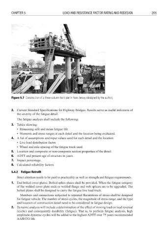
Figure 5.7 Construction of a three-column bent pier in New Jersey (designed by the author).
2. Current Standard Specifications for Highway Bridges. Results serve as useful indicators of
the severity of the fatigue detail.
The fatigue analysis shall include the following:
3. Tables showing:
• Remaining safe and mean fatigue life
• Moments and stress ranges at each detail and the location being evaluated.
4. A list of assumptions and input values used for each detail and the location:
• Live load distribution factor
• Wheel and axle spacing of the fatigue truck used.
5. Location and composite or non-composite section properties of the detail.
6. ADTT and present age of structure in years.
7. Impact percentage.
8. Calculated reliability factors.
5.4.2 Fatigue Retrofi t
Strict attention needs to be paid to practicality as well as strength and fatigue requirements.
1. End bolted cover plates: Bolted splice plates shall be provided. When the fatigue category
of the welded cover plate ends or welded flange and web splices are to be upgraded. The
bolted plates shall be designed to carry the fatigue live load truck.
Members and connections subjected to repeated flucutations of stress shall be designed
for fatigue vehicle. The number of stress cycles, the magnitude of stress range, and the type
and location of construction detail need to be considered in fatigue design.
2. Dynamic analysis will include a determination of the effect of moving load on load reversal
(cyclic) and consequently durability (fatigue). That is, to perform fatigue analysis, high
amplitude dynamic cycles will be added to the highest ADTT over 75 years recommended
AASHTO life.