
Page 221 - Bridge and Highway Structure Rehabilitation and Repair
P. 221
196 SECTION 2 STRENGTHENING AND REPAIR WORK
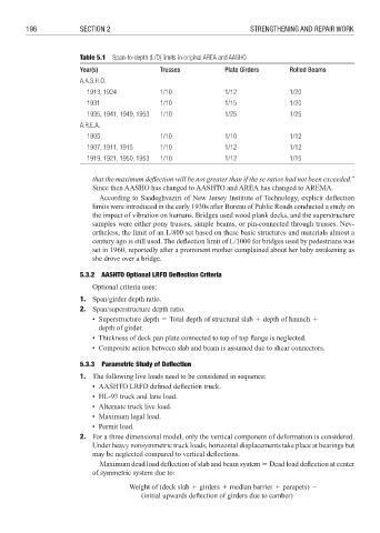
Table 5.1 Span-to-depth (L/D) limits in original AREA and AASHO
Year(s) Trusses Plate Girders Rolled Beams
A.A.S.H.O.
1913, 1924 1/10 1/12 1/20
1931 1/10 1/15 1/20
1935, 1941, 1949, 1953 1/10 1/25 1/25
A.R.E.A.
1905 1/10 1/10 1/12
1907, 1911, 1915 1/10 1/12 1/12
1919, 1921, 1950, 1953 1/10 1/12 1/15
that the maximum deflection will be not greater than if the se ratios had not been exceeded.”
Since then AASHO has changed to AASHTO and AREA has changed to AREMA.
According to Saadeghvaziri of New Jersey Institute of Technology, explicit defl ection
limits were introduced in the early 1930s after Bureau of Public Roads conducted a study on
the impact of vibration on humans. Bridges used wood plank decks, and the superstructure
samples were either pony trusses, simple beams, or pin-connected through trusses. Nev-
ertheless, the limit of an L/800 set based on these basic structures and materials almost a
century ago is still used. The deflection limit of L/1000 for bridges used by pedestrians was
set in 1960, reportedly after a prominent mother complained about her baby awakening as
she drove over a bridge.
5.3.2 AASHTO Optional LRFD Defl ection Criteria
Optional criteria uses:
1. Span/girder depth ratio.
2. Span/superstructure depth ratio.
• Superstructure depth 3 Total depth of structural slab 4 depth of haunch 4
depth of girder.
• Thickness of deck pan plate connected to top of top flange is neglected.
• Composite action between slab and beam is assumed due to shear connectors.
5.3.3 Parametric Study of Defl ection
1. The following live loads need to be considered in sequence:
• AASHTO LRFD defi ned defl ection truck.
• HL-93 truck and lane load.
• Alternate truck live load.
• Maximum legal load.
• Permit load.
2. For a three dimensional model, only the vertical component of deformation is considered.
Under heavy nonsymmetric truck loads, horizontal displacements take place at bearings but
may be neglected compared to vertical defl ections.
Maximum dead load deflection of slab and beam system 3 Dead load defl ection at center
of symmetric system due to:
Weight of (deck slab 4 girders 4 median barrier 4 parapets) 6
(initial upwards deflection of girders due to camber)