
Page 140 - Build Your Own Combat Robot
P. 140
Chapter 6:
Power Transmission: Getting Power to Your Wheels
The power transmitting capability of a V-belt is dependent on the belt tension 121
and the angle of wrap around the sheave. The greater the belt tension, the greater
the torque transmitting capability. As with synchronous belts, V-belts are avail-
able only in fixed lengths. To determine which size of V-belt to use, you should
consult the belt specification datasheets from the belt manufacturer.
For combat robots, V-belts could be used for drive belts in the power transmis-
sion and for speed reduction applications. But the most common use for V-belts is
for driving weapons. As with flat belts, using V-belts in this way will allow the belt
to slip if the weapon is stalled. With V-belts, more torque can be transmitted from
the motor to the weapons, thus making them more effective than regular flat belts.
The belt slippage when the weapon has stalled may be desirable in this situation
because the drive motors are protected from complete stall and possible burnout.
G earboxes
The compact form of a power transmission is to use a gearbox between your mo-
tors and wheels. Earlier, we talked about using gearmotors for robots. A
gearmotor consists of a gearbox mounted to an electric motor. Inside the gearbox
are gears, shafts, bearings, oil/grease, and a rigid case. A gearbox consists of pre-
cisely designed components. Within a gearbox there are various configurations of
gears to obtain the speed reduction. The common methods consists of spurs gears,
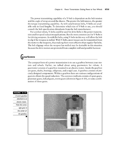
planetary gears, helical gears, worm gears (shown in Figure 6-10), or some combi-
nation of these gears.
FIGURE 6-10
A worm gearbox
attached to an
electric motor.
Note the screw-
type gear in
the center of
the gearbox.