
Page 136 - Build Your Own Combat Robot
P. 136
Chapter 6:
Power Transmission: Getting Power to Your Wheels
keyway. Some of the smaller diameter sprockets may have one or two set screws in 117
the place of a keyway. These will work adequately with a flattened area on the
shaft for lower torque applications, such as for small hobby robots. For combat
robots, use keyways on all sprockets, gears, and pulleys. Doing so is a battle-
proven method to secure components to shafts.
You might also want to apply one or more idler sprockets to take up slack in the
chain. Quite often you place your motor(s) and wheel(s) in set locations and then
apply the chain. More than likely, you’ll find that the chain is too loose (or maybe
too tight). Having a bit of slack in the chain and using a sprocket idler on a small
spring-loaded lever arm will keep the chain at a specified tightness and will pre-
vent the chain from flying outward with centrifugal force under high speeds.
When implementing a sprocket and chain system, all of the sprockets must
have the same pitch as the chain to which they are connected. When calculating
the speed and torque ratios, you should use the number of teeth instead of using
the actual diameter. If you use the sprocket diameter, use the specified pitch diam-
eter, not the outside diameter of the sprocket. The pitch diameter is the actual di-
ameter in which the chain will wrap around the sprocket.
To locate the sprockets on the robot, you can determine the distance between
the sprockets in two ways. The proper method would be to calculate the center
distances and then design the robot to accommodate the dimensions. Appendix C
shows the calculations for determining the center distances. The other method,
which is used by many beginners, is to place the two sprockets wherever you want
them and then take a long length of chain and wrap it around both sprockets,
holding the two ends in your hand. Then you cut the chain at the appropriate
place, apply the master link, and possibly use an idler sprocket to take up the
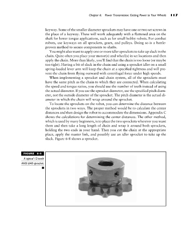
slack. Figure 6-8 shows a sprocket.
FIGURE 6-8
A typical 12-tooth
ANSI #40 sprocket.