
Page 134 - Build Your Own Combat Robot
P. 134
C hain Drive Systems Chapter 6: Power Transmission: Getting Power to Your Wheels 115
Rather than starting with some more exotic designs that use a flexible shaft or
even an articulated shaft fitted with swivel joints, let’s instead jump right to the
method that is used the most—a chain drive. This type of interconnection between
the wheels and motors offers a lot of pluses. If the proper chain is used, it has the
capacity to transfer a lot of power to the wheels. It also has the ability to take up
“slop” in the system without requiring precise spacing between the motor and
wheel/axle sprocket.
Buying the Chain
What is the proper chain for your robot? You might be tempted to use a bicycle
chain. Hey, you can pedal hard, even stand on the pedals when going uphill, and
still not break the chain. The quality of mass-marketed bicycle chains is not up to
industrial standards, however. Invest a few bucks in some good roller chain. It will
be money well spent and can save you from a few headaches in the long run.
The proper term for this type of chain is single strand roller chain. Generally,
the pitch on these types of chains ranges from 1/4 inch to 3/4 inch. A 1/2 inch pitch
means that the spacing of the sprocket’s teeth are 1/2 inch apart (or the chain’s
rollers are 1/2 inch apart). The industrial roller chain is specified with an ANSI
number, generally 25 to 80. See Table 6-1 for a list of some of the common chains.
A typical ANSI #40 industrial roller chain, for example, will have a 1/2-inch pitch
and a 5/16-inch roller width; it will have a maximum allowable load of 810 pounds;
and the chain will break when the load gets up to 4,300 pounds. The maximum al-
lowable load is based on continuous operation. Exceeding the maximum allowable
load will shorten the life of the chain. If you exceed the average tensile strength,
the chain will break.
Some builders have ganged up two sprockets on each end to double the
strength. In actuality, the strength is not quite doubled due to slight differences in
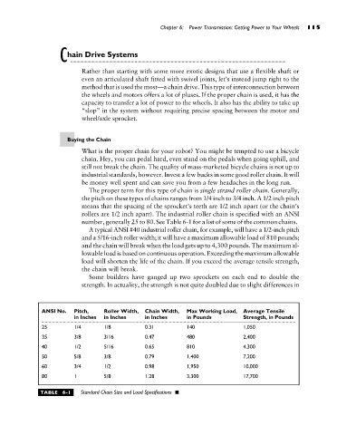
ANSI No. Pitch, Roller Width, Chain Width, Max Working Load, Average Tensile
in Inches in Inches in Inches in Pounds Strength, in Pounds
25 1/4 1/8 0.31 140 1,050
35 3/8 3/16 0.47 480 2,400
40 1/2 5/16 0.65 810 4,300
50 5/8 3/8 0.79 1,400 7,200
60 3/4 1/2 0.98 1,950 10,000
80 1 5/8 1.28 3,300 17,700
TABLE 6-1 Standard Chain Size and Load Specifications