
Page 169 - Build Your Own Combat Robot
P. 169
Build Your Own Combat Robot
150
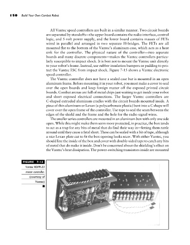
All Vantec speed controllers are built in a similar manner. Two circuit boards
are separated by standoffs—the upper board contains the radio interface, control
logic, and 5-volt power supply, and the lower board contains masses of FETs
wired in parallel and arranged in two separate H-bridges. The FETs are all
mounted flat to the bottom of the Vantec’s aluminum case, which acts as a heat
sink for the controller. The physical nature of the controller—two separate
boards and many discrete components—makes the Vantec controllers particu-
larly susceptible to impact shock. It is best not to mount the Vantec unit directly
to your robot’s frame. Instead, use rubber insulation bumpers or padding to pro-
tect the Vantec ESC from impact shock. Figure 7-15 shows a Vantec electronic
speed controller.
The Vantec controller does not have a sealed case but is mounted in an open
aluminum frame. Before mounting it in your robot, you must make a cover to seal
over the open boards and keep foreign matter off the exposed printed circuit
boards. Combat arenas are full of metal chips just waiting to get inside your robot
and short exposed electrical connections. The larger Vantec controllers are
C-shaped extruded aluminum cradles with the circuit boards mounted inside. A
piece of thin aluminum or Lexan (a polycarbonate plastic) bent into a C shape will
cover over the open frame of the controller. Use tape to seal the seam between the
edges of the shield and the frame and the hole for the radio signal wires.
The smaller series controllers are mounted in an aluminum box with only one side
open. While this might make them seem more protected, in practice, the box tends
to act as a trap for any bits of metal that do find their way in—letting them rattle
around until they cause a fatal short. These can be sealed with a bit of tape, although
a nice Lexan plate cut to fit the box opening looks nicer. With either Vantec, you
should line the inside of the box and cover with double-sided tape to catch any bits
of metal that do make it inside. Don’t be concerned about the shielding’s effect on
the Vantec’s heat dissipation. The power-switching transistors inside are mounted
FIGURE 7-15
Vantec RDFR-23
motor controller.
(courtesy of
Vantec)