
Page 170 - Build Your Own Combat Robot
P. 170
Chapter 7:
Controlling Your Motors
to the aluminum case, so enclosing the drive logic boards will not make the unit 151
overheat.
A Vantec RDFR series controller has separate power connections for the left-
and right-side motors and batteries. The high-current terminals—eight in all—are
arranged on a single terminal strip on one end of the controller. This terminal
strip, and the wiring connections to it, can be the weak point in your power train if
not properly connected. The larger Vantec controllers (RDFR32 and above) have
standard barrier blocks with eight screws to fasten down wires. Use ring-type
crimp connectors on your wires to prevent accidental shorts or connectors pulling
free of the terminal blocks. It is also a good idea to replace the soft screws used in
the Vantec terminal strips with alloy-steel, cap-head machine screws to prevent
accidentally twisting a screw head off by over tightening, and apply Loctite to
keep the screws from vibrating loose during combat.
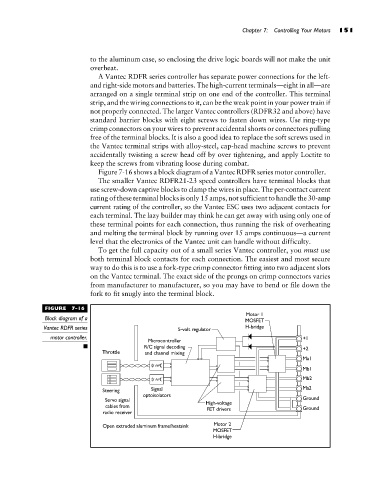
Figure 7-16 shows a block diagram of a Vantec RDFR series motor controller.
The smaller Vantec RDFR21-23 speed controllers have terminal blocks that
use screw-down captive blocks to clamp the wires in place. The per-contact current
rating of these terminal blocks is only 15 amps, not sufficient to handle the 30-amp
current rating of the controller, so the Vantec ESC uses two adjacent contacts for
each terminal. The lazy builder may think he can get away with using only one of
these terminal points for each connection, thus running the risk of overheating
and melting the terminal block by running over 15 amps continuous—a current
level that the electronics of the Vantec unit can handle without difficulty.
To get the full capacity out of a small series Vantec controller, you must use
both terminal block contacts for each connection. The easiest and most secure
way to do this is to use a fork-type crimp connector fitting into two adjacent slots
on the Vantec terminal. The exact side of the prongs on crimp connectors varies
from manufacturer to manufacturer, so you may have to bend or file down the
fork to fit snugly into the terminal block.
FIGURE 7-16
Block diagram of a
Vantec RDFR series
motor controller.