
Page 189 - Build Your Own Combat Robot
P. 189
Build Your Own Combat Robot
170
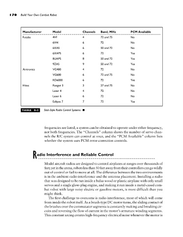
Manufacturer Model Channels Band, MHz PCM Available
Futaba 4VF 4 72 and 75 No
6VH 6 72 No
6XAS 6 50 and 72 No
6XAPS 6 72 Yes
8UAPS 8 50 and 72 Yes
9ZAS 9 50 and 72 Yes
Airtronics VG400 4 72 No
VG600 6 72 and 75 No
RD6000 6 72 Yes
Hitec Ranger 3 3 27 and 75 No
Laser 4 4 72 No
Laser 6 6 72 No
Eclipse 7 7 72 Yes
TABLE 8-2 Stick-Style Radio Control Systems
frequencies are listed, a system can be obtained to operate under either frequency,
not both frequencies. The “Channels” column shows the number of servo chan-
nels the R/C system can control at once, and the “PCM Available” column lists
whether the system uses PCM error-correction controls.
R adio Interference and Reliable Control
Model aircraft radios are designed to control airplanes at ranges over thousands of
feet;yetinthearena,robotslessthan50feetawayfromtheircontrollerscangowildly
out of control or fail to move at all. The difference between the two environments
is in the ambient radio interference and the antenna placement. Installing a radio
that was designed to be run inside a balsa wood or plastic airplane with only small
servos and a single glow-plug engine, and making it run inside a metal-cased com-
bat robot with large noisy electric or gasoline motors, is more difficult than you
might think.
The first challenge to overcome is radio interference, most of which will come
from inside the robot itself. As a brush-type DC motor turns, the sliding contact of
the brushes over the commutator segments is constantly making and breaking cir-
cuits and reversing the flow of current in the motor’s armature winding segments.
This constant arcing creates high-frequency electrical noise whenever the motor is