
Page 69 - Build Your Own Combat Robot
P. 69
Build Your Own Combat Robot
50
FIGURE 3-5
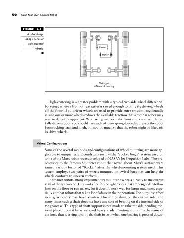
A robot design
using a series of
side-mounted
wheels.
High-centering is a greater problem with a typical two-side-wheel differential
bot setup, where a front or rear caster is raised enough to bring the driving wheels
off the floor. If all driven wheels are used to provide extra traction, accidentally
raising one or more wheels reduces the available traction that a combat robot may
need to defeat its opponent. When using casters in the front and rear of a differen-
tially driven robot, you should have each of them spring-loaded to prevent the robot
from rocking back and forth, but not too much so that the robot might be lifted off
its drive wheels.
Wheel Configurations
Some of the several methods and configurations of wheel mounting are more ap-
plicable to unique terrain conditions such as the “rocker bogie” system used on
some of the Mars robot rovers developed at NASA’s Jet Propulsion Labs. The pre-
decessors to the famous Sojourner robot that roved about Mars’s surface were
named various forms of “Rocky,” after the wheel-mounting system used. This
system employs two pairs of wheels mounted on swivel bars that can help the
wheels conform to uneven surfaces.
In smaller robots, many experimenters mount the wheels directly to the output
shaft of the gearmotor. This works fine for the light robots that are designed to follow
lines on the floor or run mazes, but it doesn’t work well for larger machines, espe-
cially combat robots that take a lot of abuse in their operation. The output shaft of
most gearmotors may have a sintered bronze bushing on the output side, and
many times such a shaft does not have any sort of bearing on the internal side of
the gearcase. This type of shaft support is not made to take the side-bending mo-
ment placed upon it by wheels and heavy loads. Bending moment is the name of
the force that is trying to snap the shaft in two when one bearing is pressed down-