
Page 107 - Build Your Own Quadcopter_ Power Up Your Designs with the Parallax Elev-8
P. 107
86 Bu il d Y o ur O w n Q u a d c o p t e r
One difference between the PreciseBlinker1 program and the FastBlinker1 program is
that the statement _XINFREQ = 5_000_000 in the CON section has been removed, and the
statement _CLKFREQ = 80_000_000 has been inserted. This statement specifies to Spin
the desired clock frequency, which is then used to derive the corresponding _XINFREQ from
the _CLKMODE value and the PLL multiplier. You can only specify either _XINFREQ or _
CLKFREQ but not both, or Spin will return an error.
The next change is insertion of the statement oneMilliSec = _CLKFREQ/1000. The
constant oneMilliSec now represents the total number of clock cycles that must pass in a
one-millisecond time interval. You no longer have to explicitly relate clock cycles to time;
just use the oneMilliSec constant.
The last change in PreciseBlinker1 affects how the Delay value is passed to the LED
object. In the Main section, both Delay values have been changed from 6_000_000 and
4_000_000 hard-coded cycle counts to 75 × oneMilliSec and 50 × oneMilliSec,
respectively. Now all you need do is focus on the desired time delay and not on counting
clock cycles. This makes for much more pleasant code development.
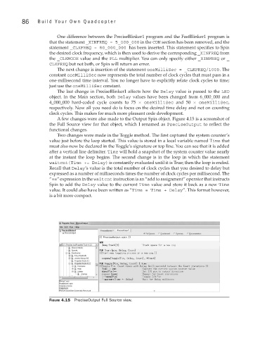
A few changes were also made to the Output Spin object. Figure 4.15 is a screenshot of
the Full Source view for that object, which I renamed as PreciseOutput to reflect the
functional changes.
Two changes were made in the Toggle method. The first captured the system counter’s
value just before the loop started. This value is stored in a local variable named Time that
must also now be declared in the Toggle’s signature or top line. You can see that it is added
after a vertical line delimiter. Time will hold a snapshot of the system counter value nearly
at the instant the loop begins. The second change is in the loop in which the statement
waitcnt(Time += Delay) is constantly evaluated until it is True; then the loop is ended.
Recall that Delay’s value is the total number of clock cycles that you desired to delay but
expressed as a number of milliseconds times the number of clock cycles per millisecond. The
“+=” expression in the waitcnt instruction is an “add to assignment” operator that instructs
Spin to add the Delay value to the current Time value and store it back as a new Time
value. It could also have been written as “Time = Time + Delay”. This format however,
is a bit more compact.
Figure 4.15 PreciseOutput Full Source view.