
Page 111 - Build Your Own Quadcopter_ Power Up Your Designs with the Parallax Elev-8
P. 111
90 Bu il d Y o ur O w n Q u a d c o p t e r
The local reference name is servo, and it represents the Spin file named PropBOE Servos.
The Set method in this file controls the PWM waveform. The first argument is the GPIO pin,
which is 14 in this case, and the second number is an offset. The offset represents a number
that will range from −1000 to +1000. This offset can be thought of as a direct control of the
pulse width where a 0 offset would be a 1.5 ms pulse, a −1000 would be a 0.5-ms pulse, and
a +1000 would be a 2.5 ms pulse. Thus, the offset is really the number of microseconds that
you want the pulse to deviate from the central 1.5-ms value. Any integer in the range from
−1000 to +1000 will proportionally set the pulse width.
Most standard servos are designed to operate with this PWM technique. Sending a
2.5-ms pulse train to a servo designed to change angular position will cause it to rotate 90°
in a clockwise direction from the neutral position. Similarly, sending a 0.5-ms pulse train will
cause it to rotate 90° in a counterclockwise direction from the neutral position. Sending a
1.5-ms pulse train will keep the servo in its neutral position.
Sending the same type of pulses to a continuous rotation servo will cause angular
velocity changes in which a 2.5-ms pulse would be the maximum speed in a clockwise
direction, a 0.5-ms pulse would be the maximum speed in a counterclockwise direction, and
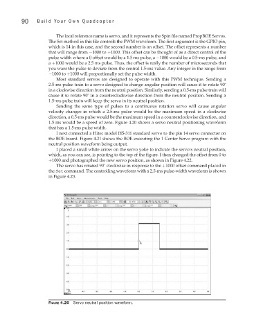
1.5 ms would be a speed of zero. Figure 4.20 shows a servo neutral positioning waveform
that has a 1.5-ms pulse width.
I next connected a Hitec model HS-311 standard servo to the pin 14 servo connector on
the BOE board. Figure 4.21 shows the BOE executing the 1 Center Servo program with the
neutral position waveform being output.
I placed a small white arrow on the servo yoke to indicate the servo’s neutral position,
which, as you can see, is pointing to the top of the figure. I then changed the offset from 0 to
+1000 and photographed the new servo position, as shown in Figure 4.22.
The servo has rotated 90° clockwise in response to the +1000 offset command placed in
the Set command. The controlling waveform with a 2.5-ms pulse-width waveform is shown
in Figure 4.23.
Figure 4.20 Servo neutral position waveform.