
Page 113 - Build Your Own Quadcopter_ Power Up Your Designs with the Parallax Elev-8
P. 113
92 Bu il d Y o ur O w n Q u a d c o p t e r
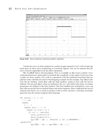
Figure 4.23 Servo maximum clockwise position waveform.
I tested the servo at other positions to confirm proper operation, but I will not take up
book space to show servo positioning or waveform figures. You can be assured that the
servo correctly responded to all the offset commands.
The PropBOE Servos Documentation View is available on this book's website www
.mhprofessional.com/quadcopter to illustrate the complexity of this object. It also provides
a guide for those readers who wish to experiment with the additional functions that are
present in the code but not used in the foregoing example. In the example, Top Object calls
only the Set method, which then calls the Start method, which in turn calls the Servos
method. The pin and offset values are defined in the Set call, while some basic waveform
parameters are defined in the Start method. The Start method also instantiates a new cog
that will execute the Servos method where real action happens. I have replicated the Servos
method code below, not so much to analyze it, but to show you how a real-time waveform
generator may be created using the Spin language.
PRI servos | t, i, ch
t := cnt
repeat
i := -1
repeat until i == 13
repeat ch from 0 to 1
if ++i =< _servoCnt
outa[_pinList[i]]~
dira[_pinList[i]]~~
spr[CTR + ch] := (%000100 << 26) & $FFFFFF00 |
_pinList[i]
spr[FRQ + ch] := spr[PHS + ch] := 1