
Page 171 - Build Your Own Quadcopter_ Power Up Your Designs with the Parallax Elev-8
P. 171
150 Bu il d Y o ur O w n Q u a d c o p t e r
registers. It is quite possible to resolve timing down to a 12.5-nanosecond (ns) interval by using
an 80-MHz system clock with the cog counters. That is impressive measurement accuracy.
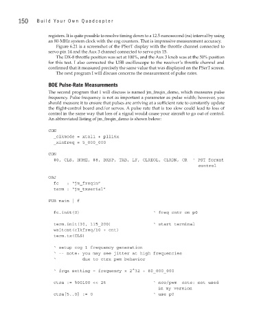
Figure 6.21 is a screenshot of the PSerT display with the throttle channel connected to
servo pin 14 and the Aux 3 channel connected to servo pin 15.
The DX-8 throttle position was set at 100%, and the Aux 3 knob was at the 50% position
for this test. I also connected the USB oscilloscope to the receiver’s throttle channel and
confirmed that it measured precisely the same value that was displayed on the PSerT screen.
The next program I will discuss concerns the measurement of pulse rates.
BOE Pulse-Rate Measurements
The second program that I will discuss is named jm_freqin_demo, which measures pulse
frequency. Pulse frequency is not as important a parameter as pulse width; however, you
should measure it to ensure that pulses are arriving at a sufficient rate to constantly update
the flight-control board and/or servos. A pulse rate that is too slow could lead to loss of
control in the same way that loss of a signal would cause your aircraft to go out of control.
An abbreviated listing of jm_freqin_demo is shown below:
CON
_clkmode = xtal1 + pll16x
_xinfreq = 5_000_000
CON
#0, CLS, HOME, #8, BKSP, TAB, LF, CLREOL, CLRDN, CR ‘ PST format
OBJ
fc : “jm_freqin”
term : “jm_txserial”
PUB main | f
fc.init(0) ‘ freq cntr on p0
term.init(30, 115_200) ‘ start terminal
waitcnt(clkfreq/10 + cnt)
term.tx(CLS)
‘ setup cog 1 frequency generation
‘ -- note: you may see jitter at high frequencies
‘ due to ctrx pwm behavior
‘ frqx setting = frequency × 2^32 ÷ 80_000_000
ctra := %00100 << 26 ‘ nco/pwm note: not used
version
ctra[5..0] := 0 ‘ use p0