
Page 39 - Build Your Own Quadcopter_ Power Up Your Designs with the Parallax Elev-8
P. 39
18 Bu il d Y o ur O w n Q u a d c o p t e r
is why it is critical to ensure that you mount the correct propeller on a motor whose rotation
matches the propeller's maximum r/min rating.
Sharp-eyed readers may have spotted a copter with three booms on the bottom row,
center of Figure 2.4. Naturally, this would indicate an unbalanced torque arrangement;
however, the “Y6” has a clever trick to counteract the odd number of booms. At the end of
each boom is one motor that drives two propellers, one at the top and one at the bottom. The
top propeller turns CW, while the bottom propeller turns CCW, thus cancelling the top
propeller’s torque effect. Another more complex approach is to have two motors mounted at
the end of each boom: one driving the top propeller and the other driving the bottom one.
Either approach enables a multirotor copter to have an odd number of booms if so desired.
The quadcopter configuration on the bottom left is known as an “X8” because it has two
propellers at the end of each boom. Either one motor drives both propellers, or there are
two motors, one to drive each propeller. Having twice the number of propellers increases the
available thrust substantially, but at the expense of requiring a lot more power for every
motor as compared to a regular four-bladed quadcopter.
Flight Controls
It would be useful now to describe how normal airplane flight controls function before
describing how the quadcopter flight path is controlled. The reason is simply that the radio-
controlled (R/C) system is set for controlling an airplane, not for controlling the quadcopter,
and it is important for you to know the “translation” that takes place when you input a
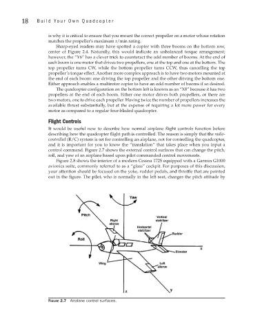
control command. Figure 2.7 shows the external control surfaces that can change the pitch,
roll, and yaw of an airplane based upon pilot commanded control movements.
Figure 2.8 shows the interior of a modern Cessna 172S equipped with a Garmin G1000
avionics suite, commonly referred to as a “glass” cockpit. For purposes of this discussion,
your attention should be focused on the yoke, rudder pedals, and throttle that are pointed
out in the figure. The pilot, who is normally in the left seat, changes the pitch attitude by
Figure 2.7 Airplane control surfaces.