
Page 220 - Build Your Own Transistor Radios a Hobbyists Guide to High-Performance and Low-Powered Radio Circuits
P. 220
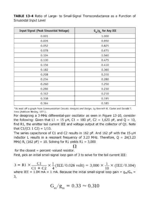
TABLE  13-4 Ratio  of Large- to  Small-Signal  Transconductance  as  a  Function  of

            Sinusoidal Input Level


                 Input Signal (Peak Sinusoidal Voltage)                     Gjgm for Any lEE

                                 0.001                                            1.000
                                 0.026                                            0.950
                                 0.052                                            0.825

                                 0.078                                            0.675
                                 0.104                                            0.560

                                 0.130                                            0.475
                                 0.156                                            0.410
                                 0.182                                            0.360

                                 0.208                                            0.310
                                 0.234                                            0.280

                                 0.260                                            0.250
                                 0.286                                            0.230
                                 0.312                                            0.210

                                 0.338                                            0.195
                                 0.364                                            0.185

            * As read  off a graph from  Communication Circuits: Analysis and Design,  by  Kenneth  K. CLarke  and  Donald T.
            Hess  (Addison-Wesley, 1971).
            For  designing  a 3-MHz  differential-pair oscillator as  seen  in  Figure  13-10,  consider
            the foUowing:  Given  that L1  = 15  IJH,  Cl = 180  pF,  C2  = 1,620 pF,  and  Q = 10,

            find  Rl, the emitter tail  current lEE  and  voltage output at the collector of Q1.  Note
            that Cl/(Cl 1 C2) = 1/10.
            The  series capacitance  of Cl and  C2  results  in  162 pF.  And  162 pF  with  the  15-IJH
            inductor  L results  in  a  resonant  frequency  of 3.23  MHz.  Therefore,  Q = 2n(3.23
            MHz)  RL  (162 pF) = 10. Solving for Rl yields R1  = 3,000


             for the closest = percent-valued resistor.
            First, pick an  initial small-signal loop gain of 3 to solve for the tail current lEE:


                       x              . X  1  I     / .  2       It  =  ~                          /  .  04)
                                     2     4                                         1
            where lEE = 1.04 mA  ~ 1 mA.  Because the initial small-Signal  loop gain = gm/Gm  =

            3,