
Page 226 - Build Your Own Transistor Radios a Hobbyists Guide to High-Performance and Low-Powered Radio Circuits
P. 226
Vin 1
onli r
Output
y
Viln 2
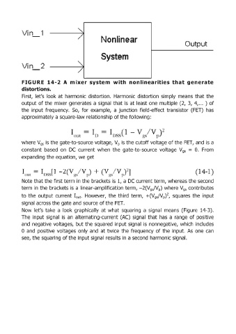
FIGURE 14-2 A m ixer system with nonlinearities that generate
distortions"
First, let's look at harmonic distortion. Harmonic distortion simply means that the
output of the mixer generates a signal that is at least one multiple (2, 3, 4, ... ) of
the input frequency. So, for example, a junction field-effect transistor (FET) has
approximately a square-law relationship of the following:
/
I
III D .
where V gs is the gate-to-source voltage, V p is the cutoff voltage of the FET, and is a
constant based on DC current when the gate-ta-source voltage Vgs = O. !From
expanding the equation, we get
-2 +
I( I) ' I
Note that the first term in the brackets is 1, a DC current term, whereas the second
term in the brackets is a linear-amplification term, - 2(Vg JVp) where V9S contributes
to the output current lout. However, the third term, +(V gJV p)2, squares the input
signal across the gate and source of the FET.
Now let's take a look graphically at what squaring a signal means (Figure 14-3),
The input signal is an alternating-current (AC) signal that has a range of positive
and negative voltages, but the squared input signal is nonnegative, which includes
o and positive voltages only and at twice the frequency of the input. As one can
see, the squaring of the input signal results in a second harmonic signal.