
Page 227 - Build Your Own Transistor Radios a Hobbyists Guide to High-Performance and Low-Powered Radio Circuits
P. 227
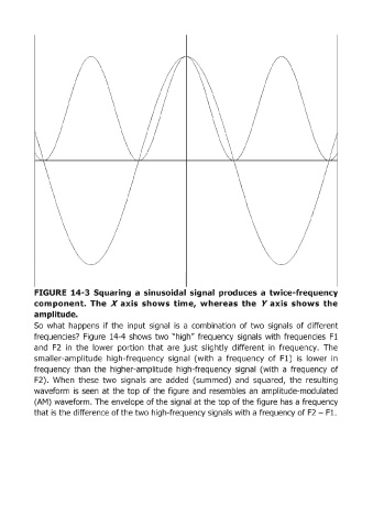
FIGURE  14-3 Squaring  a  sinusoidal  signal  produces  a  twice-frequency
            component.  The  X  axis  shows  time,  whereas  the  Yaxis  shows  the
            amplitude.
            So  what  happens  if the  input signal  is  a combination  of two  signals  of different

            frequencies?  Figure  14-4 shows  two "high" frequency  signals  with  frequencies  F1
            and  F2  in  the  lower  portion  that  are  just  slightly  different  in  frequency.  The
            smaller-amplitude  high-frequency  signal  (with  a  frequency  of  Fl)  is  lower  in
            frequency  than  the  higher-amplitude  high-frequency  signal  (with  a  frequency  of
            F2).  When  these  two  signals  are  added  (summed)  and  squared,  the  resulting

            waveform  is  seen  at the  top  of the  figure  and  resembles  an  amplitude-modulated
            (AM) waveform.  The envelope of the signal at the top of the figure has a frequency
            that is the difference of the two high-frequency signals with a frequency of F2 - F1.