
Page 235 - Build Your Own Transistor Radios a Hobbyists Guide to High-Performance and Low-Powered Radio Circuits
P. 235
X
I I
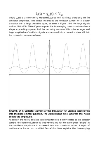
where gm(t) is a time-varying transconductance with its shape depending on the
oscillator amplitude. This shape resembles the collector current of a bipolar
transistor with a large overdrive signal, as seen in Figure 14-6. For large signals
such as 100 mV to 200 mV peak to peak, the time-varying transconductance has a
shape approaching a pulse. And the narrowing nature of this pulse as larger and
larger amplitudes of oscillator signals are combined into a transistor mixer will limit
the conversion transconductance.
·5
FIGURE 14-6 Collector current of the transistor for various input levels
into the base-emitter junction. The Xaxis shows time, whereas the Yaxis
shows the amplitude.
As seen in the figure, because transconductance is directly related to the collector
current, the transconductance is time-varying and has the same pulse "shape" as
the OSCillator amplitude is increased into the transistor mixer. A topic of
mathematics known as modified 8esse/ functions explains the time-varying