
Page 238 - Build Your Own Transistor Radios a Hobbyists Guide to High-Performance and Low-Powered Radio Circuits
P. 238
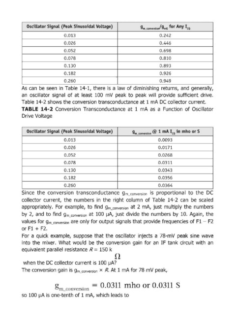
Oscillator SignaL  (Peak Sinusoidal Voltage)             g       .  /g  for Any I
                                                                         . m_conversIon  . mQCQ
                                 0.013                                            0.242
                                 0.026                                            0.446

                                 0.052                                            0.698
                                 0.078                                            0.810
                                 0.130                                            0.893

                                 0.182                                            0.926
                                 0.260                                            0.949
            As  can be  seen  in Table  14-1, there  is a law of diminishinQi  returns,  and  generally,
            an  oscillator  signal  of at  least  100  mV  peak  to  peak  will  provide  sufficient  drive.

            Table 14-2 shows the conversion transconductance at 1 mA DC collector current.
            TABLE  14-2 Conversion  Transconductance  at  1  mA  as  a  Function  of Oscillator
            Drive Voltage


               Oscillator SignaL  (Peak Sinusoidal Voltage)         9m3 0nversion@  1 mA Ica in  mho or S

                                 0.013                                           0.0093
                                 0.026                                           0.0171
                                 0.052                                           0.0268

                                 0.078                                           0.0311
                                 0.130                                           0.0343

                                 0.182                                           0.0356
                                 0.260                                           0.0364
            Since  the  conversion  transconductance  gm_conversion is  proportional  to  the  DC

            collector  current,  the  numbers  in  the  right  column  of Table  14-2  can  be  scaled
            appropriately.  For  example,  to  find  gm_conversion at 2  mA,  just multiply  the  numbers
            by  2,  and  to find gm_conversion at  100  ~A, just divide  the  numbers by  10. Again,  the
            values for gm_conversion are only for output  signals that provide frequencies of Fl - F2

            or Fl + F2.
            For  a  quick  example,  suppose  that the  oscillator  injects  a  78-mV  peak  sine  wave
            into  the  mixer.  What would  be  the  conversion  gain  for  an  IF tank circuit  with  an
            equivalent  parallel resistance  R = 150 k


             when the DC collector current is  100  ~A?

            The conversion gain  is gm_conversion X  R.  At 1 mA for 78 mV peak,


            so  100 IJA is one-tenth of 1 mA, which  leads to