
Page 241 - Build Your Own Transistor Radios a Hobbyists Guide to High-Performance and Low-Powered Radio Circuits
P. 241
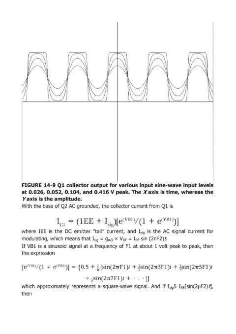
FIGURE  14-9 Q1 collector output for various input sine-wave input levels
            at 0.026, 0.052, 0.104, and 0.416 V peak. The X axis is time, whereas the
             Yaxis is the amplitude.
            With the base of Q2 AC grounded, the collector current from Ql is


                                                                     /       +
                                , J
            where  lEE  is  the  DC  emitter "tail" current,  and  I sig  is  the  AC  signal  current  for

            modullating, which  means that I sig  = gm3  X  V RF  = IRF sin (2nF2)t
            If VBl  is a sinusoid  signal at a frequency of Fl at about 1 volt peak to peak,  then
            the expression


            [  (  B1)/  1  +   (\, BI ) ]  =  {   I  + ~ i  in 211"'   t +i  in  211   t + ~ 'in 21T        t
                                                  'IT
                                            +~in21T7'  1)  + .. . ]}

            which  approximately  represents  a square-wave  signal.  And  if IsigS  IRF[sin(2IJF2)tJ,
            then