
Page 245 - Build Your Own Transistor Radios a Hobbyists Guide to High-Performance and Low-Powered Radio Circuits
P. 245
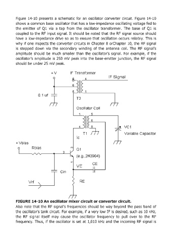
Figure  14-10  presents  a schematic  for an  oscillator converter  circuit.  Figure  14-10

            shows a common  base oscillator that has a low-impedance oscillating voltage fed  to
            the  emitter  of Ql  via  a  tap  from  the  oscillator  transformer.  The  base  of Q1  is
            coupled  to the  RF  input signal.  It should  be  noted  that the  RF  signal  source should
            have  a low-impedance drive  so  as  to ensure  that oscillation  occurs  reliably. This  is
            why  if one  inspects the converter circuits in  Chapter  8 orChapter 10,  the  RF  signal
            is  stepped  down  via  the  secondary  winding  of the  antenna  coil.  The  RF  signal's
            amplitude  should  be  much  smaller  than  the  oscillator's  signal.  For  example,  if the

            oscillator's  amplitude  is  250  mV  peak  into the  base-emitter junction,  the  RF  signal
            should  be under 25 mV peak.


                                                                            IF Signal


                                                                                       VC1

                                                                                       Variable  Capacitor


            FIGURE 14-10 An oscillator mixer circuit or converter circuit.

            Also  note that the  RF  signal's  frequencies  should  be  way  beyond  the  pass  band  of
            the oscillator's tank circuit.  For example,  if a very low IF is desired, such as  10 kHz,
            the  RF  signal  itself  may  cause  the  oscillator  frequency  to  pullover to  the  RF
            frequency.  Thus,  if the  oscillator is  set  at  1,OlD  kHz  and  the  incoming  RF  signal  is