
Page 243 - Build Your Own Transistor Radios a Hobbyists Guide to High-Performance and Low-Powered Radio Circuits
P. 243
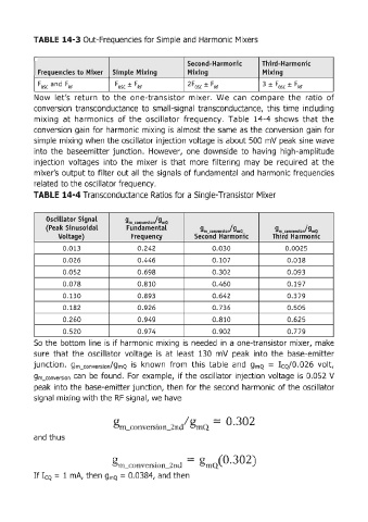
TABLE  14-3 Out-Frequencies for Simple and  Harmonic Mixers


                                                              Second-Harmonic         Third-Harmonic
             Frequendes to  Mixer  SimpLe  Mixing             Mixing                  Mixing

             Fosc  and  FRF           FOS(  ±  FRF            2Fosc ±  FRF            3±Fosc ±FRF
            Now  let's  return  to  the  one-transistor  mixer.  We  can  compare  the  ratio  of
            conversion  transconductance  to  small-signal  transconductance,  this  time  including
            mixing  at  harmonics  of the  oscillator  frequency.  Table  14-4  shows  that  the

            conversion  gain  for harmonic  mixing  is  almost the  same  as  the conversion  gain  for
            simple  mixing  when  the oscillator injection voltage is about 500  mV peak sine wave
            into  the  baseemitter  junction.  However,  one  down  side  to  having  high-amplitude
            injection  voltages  into  the  mixer  is  that  more  filtering  may  be  required  at  the
            mixer's  output to filter out all  the signals of fundamental  and  harmonic frequencies
            related  to the oscillator frequency.

            TABLE  14-4 Transconductance Ratios for a Single-Transistor Mixer


                Oscillator Signal
                                          g m_conversion! 9mQ
                (Peak Sinusoidal          FundamentaL
                                                                  gm  conversioj9 mQ      9 m_conversio./9 mQ
                    Voltage)                Frequency           Second  Harmonic         Third  Harmonic
                     0.013                    0.242                   0.030                  0.0025
                     0.026                    0.446                   0.107                   0.018
                     0.052                    0.698                   0.302                   0.093

                     0.078                    0 .810                  0.460                   0.197
                     0.130                    0 .893                  0.642                   0.379

                     0.182                    0 .926                  0.736                   0.505
                     0.260                    0 .949                  0.810                   0.625
                     0.520                    0.974                   0.902                   0.779
            So  the  bottom  line  IS  If harmonic  mixing  IS needed  In  a one-transistor mixer,  make

            sure  that  the  oscillator  voltage  is  at  least  130  mV  peak  into  the  base-emitter
            junction.  gm_coovecs;oo/gmQ  is  known  from  this  table  and  gmQ  =  I cQ / 0.026  volt,
            gm_coove,;;oo  can  be  found.  For  example,  if the oscillator  injection  voltage  is  0.052  V
            peak  into the base-emitter junction,  then  for the  second  harmonic of the oscillator

            signal  mixing with  the RF  signal, we have


                                                             / g
                                      g  nl_COl1vcrsion.-2nd  mQ      =  0.302

            and thus


                                     gm_con"crsion.-2nd  =  gmQCO.302)

            If ICQ  =  1 mA, then gmQ  = 0.0384, and then