
Page 247 - Build Your Own Transistor Radios a Hobbyists Guide to High-Performance and Low-Powered Radio Circuits
P. 247
+v
O. I ut
IF Transformer
T1
~-----:1&-1 t=
IF Output
rh
LI Rl
C3
+VDlas_,
Cl VC_Osc
Rbl 01 02
MP MP
0.1 uf C2 Rb2
J +Vblas_l
Vosc
0.1 ut
Vrf
) 03
Rb3
RE
+VDlas 2
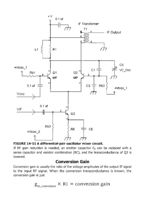
FIGURE 14-11 A differential-pair oscillator mixer circuit.
If RF gain reduction is needed, an emitter capacitor C, can be replaced with a
series capacitor and resistor combination (RC), and the transconductance of Q3 is
lowered.
Conversion Gain
Conversion gain is usually the ratio of the voltage amplitudes of the output IF signal
to the input RF signal. When the conversion transconductance is known, the
conversion gain is just
g l1L.COOvCrSlon X RI - conversion gain