
Page 248 - Build Your Own Transistor Radios a Hobbyists Guide to High-Performance and Low-Powered Radio Circuits
P. 248
where Rl is the equivalent load resistance (usually) in a parallel LC tank circuit. If
the mixer's output current is connected to a tapped transformer, then the turns
ratio must be taken into consideration. For example, many IF transformers have a
turns ratio of 3: 1 in the primary winding. If the IF transformer has an equivalent
parallel resistance of 200 k
2
, then the resistance at the low-side tap is (1/3 ) X 200 k
, or 22.2 k
= Rl. AliSO note that the output signal at the secondary winding of the IF
transformer will be lower than at the primary winding owing to the step-down ratio.
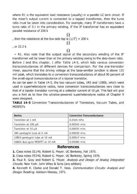
Before I end this chapter, I offer Table 14-5, which lists various conversion
transconductances of different devices for comparison. For the one-transistor
mixer, assume that the driving voltage at the base-emitter junction is above 125
mV peak, which translates to a conversion transconductance of about 90 percent of
the small-signal transconductance of a bipolar transistor.
As can be seen in Table 14-5, the two vacuum tubes, 1R5 and 12BE6, which were
used in superheterodyne radios, have conversion transconductances very close to
that of a bipolar transistor running at a collector current of 10 JJA. This fact will give
you a hint as to how the ultralow-powered superheterodyne radios of Chapter 9
were designed.
TABLE 14-5 Conversion Transconductances of Transistors, Vacuum Tubes, and
MOSFETs
Device Conversion Transconductance
Transistor at 1 mA 0.0345 mho
Translstor at 100 ~A 0.00345 mho
TranSlstor at 10 !-lA 0.00035 mho
1 R5 pentagrid tube at 5 mA 0.00030 mho
128E6 pentagrid tube at 10 mA 0.00047 mho
40604 dual-gate MOSFET at 10 mA 0.00280 mho
References
1. Class notes EE140, Robert G. Meyer. UC Berkeley, Fall 1975.
2. Class notes EE240, Robert G. Meyer. UC Berkeley, Spring 1976.
3. Paul R. Gray and Robert G. Meyer. Analysis and Design of Analog Integrated
Circuits. New York: John Wiley & Sons (any edition).
4. Kenneth K. Clarke and Donald T. Hess. Communication Circuits: Analysis and
Design. Reading: Addison-Wesley, 1971.