
Page 251 - Build Your Own Transistor Radios a Hobbyists Guide to High-Performance and Low-Powered Radio Circuits
P. 251
Ilnput Signal Output
SamplingS!ignal
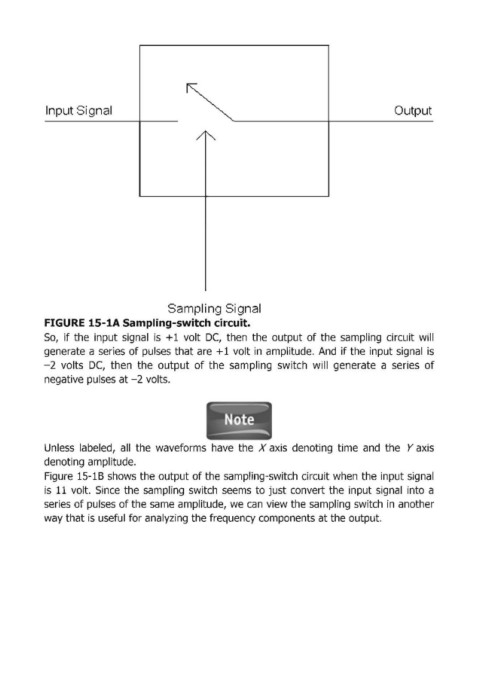
FIGURE 15-1А Sam!pling-switch circuit.
50, if the input signal is + 1 volt ОС, then the output of the sampling circuit will
generate а series of pulses that аге + 1 volt in amplitude. And if the input signal is
- 2 volts ОС, then the output of the sampling switch will generate а series of
negative pulses at -2 volts.
Unless labeled, all the waveforms have the Х axis denoting time and the У axis
denoting amplitude.
Figuгe 15-1В shows the output of the sampling-switch ciгcuit when the input signal
is 11 volt. Since the sampling switch seems to just сопуегt the input signal into а
seгies of pulses of the same amplitude, we сап view the sampling switch in anotheг
way that is useful for analyzing the frequency components at the output.