
Page 256 - Build Your Own Transistor Radios a Hobbyists Guide to High-Performance and Low-Powered Radio Circuits
P. 256
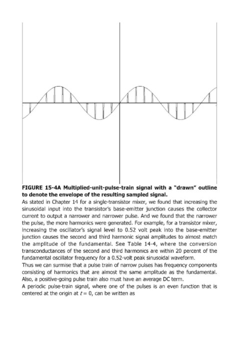
FIGURE  15-4А Multiplied-unit-pulse-train  signal  with  а "drawn" outline
            to denote the envelope of the resulting sampled signal.
            As  stated  in  Chapter  14 for  а single-transistor mixer,  we  found  that increasing  the
            sinusoidal  input  into  the  transistor's  base-emitter junction  causes  the  collector
            current to output а narrower and  narrower pulse.  And  we  found  that the  narrower

            the pulse, the  тоге harmonics were generated.  For example, for а transistor mixer,
            increasing  the  oscillator's  signal  level  to  0.52  volt  peak  into  the  base-emitter
            junction  causes  the  second  and  third  harmonic signal  amplitudes to  almost  match
            the  amplitude  of the  fundamental.  See  ТаЫе 14-4,  where  the  conversion
            transconductances  of the second  and  third  harmonics  аге within  20  percent of the
            fundamental oscillator frequency for а O.52-volt peak sinusoidal waveform.

            Thus we  сап surmise that а pulse train of narrow pulses  has frequency components
            consisting  of harmonics  that  аге almost  the  same  amplitude  as  the  fuлdаmепtаl.
            Also,  а positive-going pulse train also must have ап average  ОС term.
            А periodic  pulse-train  signal,  where  опе of the  pulses  is  ап even  function  that  is
            centered at the origin at t = О, сап Ье written as