
Page 242 - Build Your Own Transistor Radios a Hobbyists Guide to High-Performance and Low-Powered Radio Circuits
P. 242
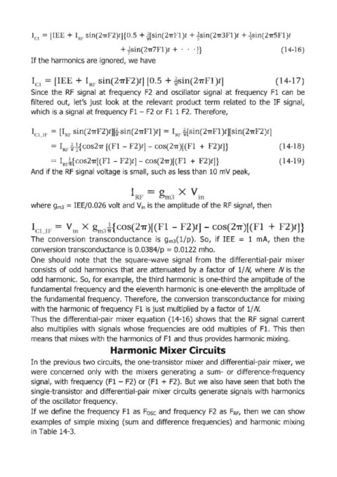
I ,) =  lI ' · +  I  ,  in(21T ' 2)l]{  .5 + ~[  in(21T  1)l + ~.  in(21T  ' 1)l + ~ in(21T  ;~ 1)1
                             Rt
                                            + f in  211'7  1 t +  .  . ·n                             1  -1  )


            If the harmonics are ignored, we  have


            ,  = .[       _  +       in  21T  2  t          + 2 , in  2'TT  1  t                    14 1 7
              .. 1    I   _      Rf                            T;'
            Since  the  RF  signal  at frequency  F2  and  oscillator  signal  at frequency  Fl  can  be
            filtered  out,  let's  just  look  at the  relevant  product  term  related  to  the  IF  signal,
            which  is a signal at frequency Fl - F2  or F1  1 F2.  Therefore,


            le)  I~'  =  [IIU'  in  21T  2  t][~  in 21T  1 )t]  =  I  , M in(21T  1  t][  in(21T  2)t]
                                                               Rf
                                          1 -    2  t]  -               +  2  t] }                   14-1

                   =  I RF~    -21T[     -   2)t] -       211')[  1  +  2  t] }                     (1  -1
            And  if the RF signal voltage is small, such as  less than  10 mV peak,


                                                                x
                                                                         1
            where gm3 = IEEjO.026 volt and V in  is the amplitude of the RF signal, then


                           ill  X  , ! {                          . 2)t] -         27T)l"                lJ}
              :1  II'                            271"  [  4}  -
            The  conversion  transconductance  is  gm3( l/p).  So,  if lEE  = 1  mA,  then  the

            conversion transconductance is 0.0384/p = 0.0122 mho.
            One  should  note  that  the  square-wave  signal  from  the  differential-pair  mixer
            consists  of odd  harmonics that are  attenuated  by  a factor  of 1/ N,  where  N is  the
            odd  harmonic.  So,  for example, the third harmonic is one-third the amplitude of the
            fundamental  frequency and  the eleventh  harmonic is one-eleventh the amplitude of

            the fundamental  frequency.  Therefore,  the conversion  transconductance for mixing
            with the harmonic of frequency Fl is just multiplied by a factor of 1/ N.
            Thus  the  differential-pair  mixer equation  (14-16)  shows  that the RF  signa;1 current
            also  multiplies  with  signals  whose  frequencies  are  odd  multiples  of Fl.  This then
            means that mixes with the harmonics of Fl and thus provides harmonic mixing.

                                        Harmonic Mixer Circuits

            In the previous two circuits, the one-transistor mixer and  differential-pair mixer, we
            were  concerned  only  with  the  mixers  generating  a  sum- or  difference-frequency
            signal l,  with frequency (F1  - F2)  or (Fl + F2).  But we  also have  seen  that both the
            Single-transistor and  differential'-pair mixer circuits generate signals with  harmonics
            of the oscillator frequency.
            If we  define the frequency  Fl as  Fosc  and  frequency  F2  as  F RF ,  then  we  can  show

            examples  of simple  mixing  (sum  and  difference  frequencies)  and  harmonic  mixing
            in Table 14-3.