
Page 302 - Build Your Own Transistor Radios a Hobbyists Guide to High-Performance and Low-Powered Radio Circuits
P. 302
carrieг missing at 38 kHz. At the receiver, to regenerate the 38-kНz carrier signal
for synchronous detection, а 19-kНz "pilot" signal is sепt from the radio stаtiоп. Ву
frequency multiplication of the 19-kНz pilot tone, а 38- kНz signal is generated and
then used to гесоуег the L -R aud'io signals (Figure 16-7).
Multiplier
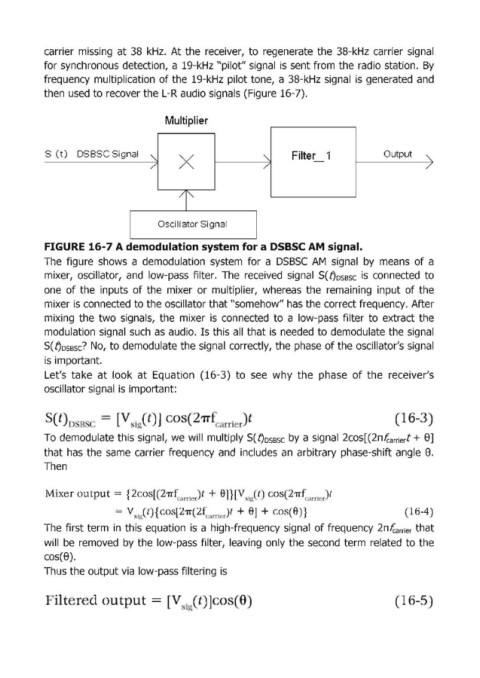
S (t) DSBSC Signal Filter 1 Output
'" Х '" - "
/
/
/
/1'"
Oscillator Signa!1
FIGURE 16-7 А demodulation system for а DSBSC АМ signal.
The figure shows а demodulation system for а DSBSC АМ sigпаl Ьу means of а
mixer, oscillator, and low-pass filter. The received signal S(t)OSBSC is connected to
опе of the inputs of themixer ог multiplier, whereas the гemaining input of the
mixer is connected to the oscillator that "somehow" has the correct frequency. After
miхiпg the two sigпаls, the mixer is соппесtеd to а low-pass filter to extract the
mоdulаtiоп sigпаl such as audio. Is this all that is needed to demodulate the signal
S( t)OSBSC? No, to demodulate the signal correctly, the phase of the oscillator's sigпаl
is important.
Let's take at look at Еquаtiоп (16-3) to see why the phase of the гeceiver's
oscillator sigпаl is imрогtапt:
t
То demiodulate this sigпаl, we will multiply S( t)OSBSC Ьу а signal 2соs[(2пfcаГГiегt + 8]
that has the same carrier frequency and includes ап arbitrary phase-shift angle 8.
Тhеп
u u = {2o'[(21Jt' ' гrir t + ]}[" i t С (211' " Т r)t
t
= V 'I.(t { [27r 2 rтl r + ] + } -4
The first term in this equation is а high-frequency signal of frequency 2пfcаГГiег that
will Ье Iremoved Ьу thie low-pass filter, leaving only the second term related to the
cos(8).
Thus the output via low-pass filtегiпg is
i1 =[ ]