
Page 303 - Build Your Own Transistor Radios a Hobbyists Guide to High-Performance and Low-Powered Radio Circuits
P. 303
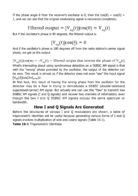
If the  phase  angle 8 from  the receiver's  oscillator is  О, tihen  the cos(8)  = cos(O)  =

            1, and we сап see that the original modulating signal  is recovered completely:


            But if the oscillator's phase is 90 degrees, the filtered  output is


            And  if the oscillator's phase  is  180 degrees off from the radio station's carrier signal
            phase, we get as the output


            [   i~  t                           11 t  r     u t  u  t]1  t in  rt  th  ph               .  t)
                                                                                                         i
            What's interesting about using  synchronous detection оп а DSBSC  АМ signal  is that
            with  the "wгопg" phase  provided  Ьу the  oscillator,  the  output of the  detector  сап
            Ье zero.  This result is almost as  if the detector does not even "see" the input signal
            [V Sig( f) ]соs(2п fcarrier) t

            At  first  look,  this  result  of having  the  wrong  phase  from  the  oscillator  for  the
            detector  тау Ье а  flaw  in  trying  to  demodulate  а  DSBSC  (doubIe-sidеЬапd
            suppressed-carrier)  АМ signal.  But actually  опе canuse this "flaw" to transmit two
            DSBSC  АМ signals (1  and Q signals)  and  recover two channel!s of information, even
            though  the  two  1 and  Q  DSBSC  АМ signals  occupy  the  same  spectrum  ог
            bandwidth.

                               How I  and Q Signals Are Generated

            Before  the  structures  of various  1 and  Q modulators  аге shown,  а  tabIe  of
            trigonometric  identities will  Ье useful  Ьесаusеgепегаtiпg various  forms  of 1 and  Q
            signa:ls involves multiplication of sine an,d cosine signals  (ТаЫе 16-1).
            ТаЫе 16-1 Trigonometгic Identities