
Page 325 - Build Your Own Transistor Radios a Hobbyists Guide to High-Performance and Low-Powered Radio Circuits
P. 325
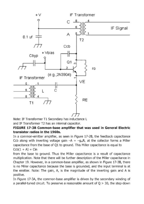
+V                           IF  Tlransformer

                                                         с
                                                                       ~ :                   IF Signal


                    0 .1 uf ,J                          А


                                                                   Т2

                                                      СсЬ

                                    + Vbias
                         С Ьур

                                                         Q1  м


                                                        2                     го

                                         (e.g "12N3904)
                 IF  Transformer                              ~
                                                                   V E
                      5_      _1

                      6             L         С

                      8         4
                         Т1  m                                        RE


            Note: IF Tгansfoгmeг Тl Secondaгy has inductance L
            and IF Tгansfoгmeг Т2 has ап inteгnal capacitoг.

            FIGURE  17-38 Common-baseamplifier that was used  in General  Electric
            transi$tor radio$ in the 1960$.
            In  а common-emitter amplifier,  as  seen  in  Figure  17-28,  the feedback capacitance
            СсЬ along  with  inveгting voltage  gain  -А = -gmRL  at the  collectoг foгms а  M il leг
            capacitance fгom the base of Ql to gгound. This  Milleг capacitance is equal to

            СсЬ(l + А) = Cin
            from  the  base  to  ground.  Thus  the  Mi lleг  capacitance  is  а result  of capacitance
            multiplication.  Note that there will  befuгther dеsсгiрtiоп of the Miller capacitance in
            Chapter 19.  However, in а common-base amplifier, as shown in  Figure  17-3В, there

            is  по Miller capacitance  because  the  base  is  grounded, and  the  input terminal  is at
            the  emitter.  Note:  The  gain,  А,  is  the  magnitude  of the  inverting  gain  and  А is
            positive.
            In Figure  17-3А, the common-base amplifier isdriven  Ьу the secondary winding  of
            а parallel-tuned ciгcuit. То preseгve а геаsопаЫе amount of Q >  ЗО, the step-down