
Page 320 - Build Your Own Transistor Radios a Hobbyists Guide to High-Performance and Low-Powered Radio Circuits
P. 320
at nodes А and С will Ье equal. The neutralizing capacitor will have the same
capacitance as СсЬ; thu5 CN = СсЬ.
However, Ьу the 1960s, tran5istors had improved, and the capacitance of СсЬ was
low enough to do without the neutralizing capacitance CN. But there аге at least а
couple of other reasons for the collector current output signal to feed into а tapped
LC circuit. Опе геа50П is to avoid oscillation Ьу setting up а lower-impedance point
at the tap 50 that the overall gain of the amplifier i5 not too high. Recall that the
im,pedance of а parallel LC circuit is very high and in practice сап Ье in the
hundreds of kiloohms at resonance.
Another reason is to avoid loading down the Q of the LC circuit. Ву u5ing а tapped
winding, апу resistive losses from the collector to the emitter of the transi5tor will
cause negligibIe ргоЫет5. Since emitter capacitor СЕ i5 ап АС 5hort to ground, the
collector to emitter resistance in the transistor will act а5 а resistor from the
collector to ground.
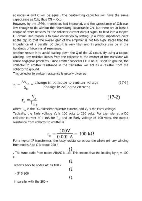
This collector to emitter resistance i5 usuallygiven as
17 ..
r =-~
()
72
---
I
()
where I CQ is the ОС quiescent collector current, and V А is the Early voltage.
Typically, the Early voltage V А is 100 volts to 250 volts. For example, at а ОС
collector curгent of 1 тА for I CQ and ап Early voltage of 100 volts, the output
resistance from collector to emitter is
For а typical IF transformer, the I05SY re5istance across the whole primary winding
from nodes А to С is about 200 k
. The turns ratio from node5 АВ/АС is 1:3. Thismeans that the loading Ьу го = 100
k
reflects back to nodes АС as 100 k
х з2 5 900
in parallel with the 200-k