
Page 317 - Build Your Own Transistor Radios a Hobbyists Guide to High-Performance and Low-Powered Radio Circuits
P. 317
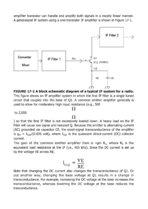
amplifier transistor сап handle and  amplify  both  signals  in  а mostly linear  таппег.

            А genera'lized IF system using  а one-transistor IF amplifier is shоwл in  Figure 17-1.


                                                                                      IF Filter 2


               Converter                                                  (")  а1
                                        IF Filter 1        Rin
                                                                             (e .g.,2N3904)
                   Mixer


                                                                              RE


            FIGURE 17-1 А bIock schematic diagram of а typicallF system for а radio.
            This figure shows  ап IF amplifier system  in  which  the first IF filteris а single tuned
            circuit  that  couples  into  the  base  of Ql.  А соттоп emitter  amplifier  generally  is
            used to allow for moderately high input re5istance (e.g.{ 500


             to 2,000


            )  50  that the first IF filter  i5  not exces5ively  loaded  down.  А heavy  load  оп the  IF

            filter will cause  low signal and  reduced Q.  Becau5e the emitter i5 alternating-current
            (АС) gгоuпdеd via  capacitoг СЕ, the small-signa'l tгапsсопduсtапсе of the amplifier
            i5  gm  ==  I CQ1/(O.026  volt),  where  I CQ1  i5  the  quiescent  direct-current  (ОС) collector
            current.

            The  gain  of the  соттоп emitter  amplifieг then  is  -gm  R L ,  where  R L  is  the
            equivalent  load  resistance  at the  IF О.е., 455  kHz).  Since  the  ОС current is  set up
            Ьу the voltage VE across RE,


                                                     <>  1

            Note  that changing  the  DC  curгent also  changes  the  transconductance  of Ql.  Ог
            put  another  way,  changing  the  base  voltage  at  Ql  re5ults  in  а  change  in
            tгапsсопduсtалсе. For example, increasing the ОС voltage at the Ьа5е increa5es the
            transconductance,  wherea5  lowering  the  ОС voltage  at  the  Ьа5е reduces  the
            tra ncond ucta  псе.