Page 313 - Build Your Own Transistor Radios a Hobbyists Guide to High-Performance and Low-Powered Radio Circuits
P. 313

М1


                                        "'-    х                   "-     Filter  1         Fiilter_ 1 Out
                                                                                -
                                        /                          /                                       "
                                                                                                           /
                                               /1


                                    Oscillator Signal О Degree
                                          Cosine Signal
              Input Si gnal
                               "-
                               /
                Vrf (t)


                                               М2


                                        "-     Х                   "-     Filter  2         Fiilter_  20ut
                                                                                -
                                        /                          /                                       "
                                                                                                           /
                                              l'


                                    Oscillator Signal 90 Degrees
                                           Sine Signal


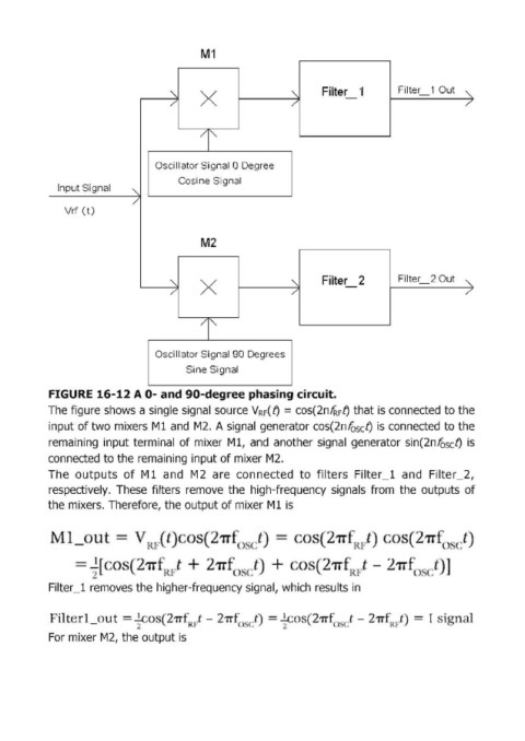
            FIGURE  16-12 А 0- and 90-degreephasing circuit.
            The figu1re shows  а single signal  source VRF( fJ  = соs(2ПlRFfJ that is connected to the
            input of two mixers  Мl and  М2. А signal  generator соs(2пfosсfJ is connected to the
            remaining  input terminal  of mixeг Мl, and  anotheг signal  generator  siп(2пfosсfJ is

            connected to the remaining input of mixer М2.
            The  outputs  of  Мl and  М2 аге connected  to  filters  Filter_l  and  Filter_2,
            respectively.  These  filteгs  remove  the  high-frequency  signals  from  the  outputs  of
            the mixeгs. Theгefoгe, the output of mixeг М 1 is


                                                                             1т

                  = ; [         211"            2  (.                      21i        - 2


            Filteг _1  removes the  higheг-frequency signal, which  гesults in


                                                                                 t -
              'lt  1                   21Т  R J - 271"  ' .~  .t   ---..'..,.....  271"'  ( .  .   11"      1
            For mixer М2, the output is
   308   309   310   311   312   313   314   315   316   317   318